

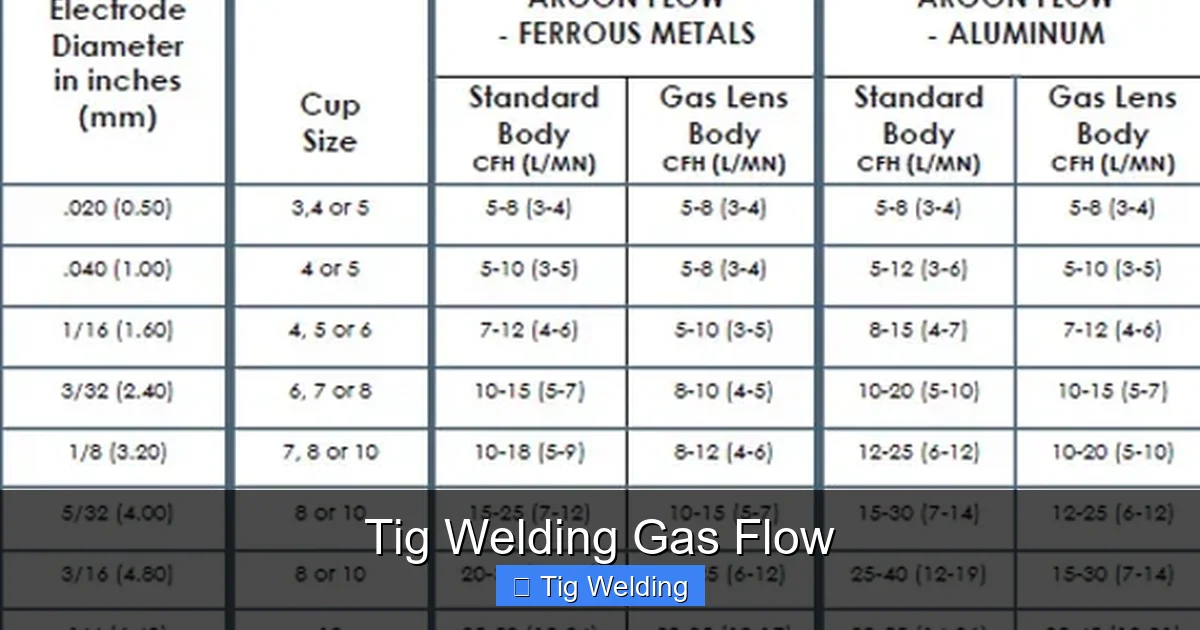
Understanding TIG welding gas flow is crucial for producing high-quality welds. This guide provides a comprehensive overview, covering everything from selecting the right gas to adjusting flow rates and troubleshooting common problems. By mastering these techniques, you’ll ensure proper shielding, prevent contamination, and achieve beautiful, strong TIG welds every time.
Key Takeaways
- Proper gas flow is essential for shielding the weld puddle from atmospheric contaminants like oxygen and nitrogen, which can cause porosity and weak welds.
- Argon is the most common shielding gas for TIG welding due to its inert nature and effectiveness in various applications.
- Flow rate is determined by factors like weld joint type, material thickness, amperage, and welding position, with higher flow rates generally needed for open joints or thicker materials.
- Incorrect gas flow can lead to porosity, oxidation, tungsten contamination, and a poorly fused weld, indicating the need for adjustment.
- A flowmeter regulator is the standard tool for controlling gas flow, allowing precise adjustment to the recommended cubic feet per hour (CFH) or liters per minute (LPM).
- Pre-flow and post-flow settings are important for purging the torch before welding and protecting the cooling tungsten and weld puddle after the arc stops.
- Regularly checking for leaks and ensuring the gas cylinder is not empty are basic but vital maintenance steps for consistent gas flow.
Tig Welding Gas Flow: Your Essential Guide to Shielding Success
Welcome, aspiring and experienced TIG welders! If you’ve ever looked at a flawless TIG weld and wondered about the secret, you’re in the right place. While torch control, amperage, and filler metal all play significant roles, one of the most vital, yet sometimes overlooked, elements is TIG welding gas flow. Getting this right is the difference between a weld that looks good and holds strong, and one that’s riddled with defects.
In this comprehensive guide, we’ll break down everything you need to know about TIG welding gas flow. We’ll cover why it’s so important, how to choose the right gas, how to set your flow rate, and what to do when things don’t go as planned. By the end of this guide, you’ll have the confidence and knowledge to dial in your gas flow for consistently superior TIG welds.
Why is Gas Flow So Important in TIG Welding?
At its core, TIG welding is an arc welding process that uses a non-consumable tungsten electrode to generate heat. The beauty of TIG lies in its precision and cleanliness. However, to maintain this cleanliness, we need to protect the molten weld puddle and the hot tungsten from the surrounding atmosphere. This is where shielding gas comes in.
Think of the shielding gas as a protective blanket. When you strike an arc, the molten metal and the tungsten electrode are exposed to the air. Air contains oxygen and nitrogen, which are highly reactive. If these gases come into contact with the molten metal, they can cause serious problems:
- Oxidation: Oxygen will react with the molten metal, forming oxides. These oxides are impurities that weaken the weld and can appear as discolored or rough surfaces.
- Porosity: When oxygen and nitrogen get trapped within the solidifying weld metal, they form gas bubbles, creating small holes called pores. Porosity significantly reduces the strength and integrity of the weld.
- Tungsten Inclusions: If the tungsten electrode is too close to the weld puddle or if the gas flow is insufficient, air can contaminate the electrode, causing it to shed small particles (tungsten inclusions) into the weld.
A proper flow of shielding gas displaces these atmospheric contaminants, creating a clean, stable arc and a pristine weld puddle. This ensures a strong, ductile, and aesthetically pleasing weld.
Choosing the Right Shielding Gas
The most common shielding gas for TIG welding is pure Argon. This is for good reason. Argon is an inert gas, meaning it doesn’t readily react with the metals being welded. It’s also relatively inexpensive and readily available.
However, depending on the material you’re welding and the desired weld characteristics, you might use other gases or mixtures:
- Pure Argon: The workhorse for TIG welding. Excellent for aluminum, magnesium, and generally all steels (carbon steel, stainless steel) for most applications, especially at lower amperages. It provides good arc stability and penetration.
- Argon/Helium Mixtures: Helium is also an inert gas, but it transfers more heat than Argon. Mixtures of Argon and Helium (e.g., 75% Argon / 25% Helium) are often used for:
- Welding thicker sections of aluminum and copper alloys, where higher heat input is needed to achieve proper fusion.
- Welding at higher travel speeds, as the increased heat input can help maintain puddle fluidity.
- Outdoor welding or in drafty conditions, as Helium is lighter than Argon and less likely to be blown away.
- Argon/Hydrogen Mixtures: These are less common for general TIG welding but can be used for specific applications, particularly on stainless steel and nickel alloys. Hydrogen can act as a “cleaning agent” and promote a brighter, cleaner bead. However, hydrogen can cause embrittlement in some steels, so caution is advised.
- Pure Helium: Used for specialized applications requiring very high heat input, like welding thick copper or for specific aluminum alloys.
For most TIG welding applications, especially if you’re just starting out or working with common metals like steel and aluminum, **pure Argon is your go-to gas.**
Understanding Your Gas Delivery System
To get your shielding gas from the cylinder to your torch, you need a few key components:
- Gas Cylinder: This is where your shielding gas is stored under high pressure.
- Regulator/Flowmeter: This is the crucial device that connects to the gas cylinder. It reduces the high cylinder pressure to a usable working pressure and, most importantly, controls the flow rate of the gas. Most TIG welding setups use a combination regulator and flowmeter.
- Hose: A durable hose connects the regulator/flowmeter to your TIG torch.
- TIG Torch: The gas flows through the torch body and out of the gas lens, which is designed to direct the gas precisely over the weld puddle.
The regulator/flowmeter is where you’ll be making your adjustments. A **flowmeter** is the preferred choice over a simple pressure regulator because it directly measures and controls the volume of gas flowing per unit of time, typically in Cubic Feet per Hour (CFH) or Liters Per Minute (LPM).
Setting the Correct Gas Flow Rate: The Art and Science
Setting the correct gas flow rate is a skill that develops with practice and understanding. There’s no single magic number; it depends on several factors:
- Material Type and Thickness: Thicker materials and those that require more heat input (like aluminum) often benefit from slightly higher flow rates.
- Joint Design: Open butt joints or V-grooves will require a wider coverage of shielding gas than a tight corner weld or a fillet weld.
- Amperage: Higher amperages generally mean a larger, hotter weld puddle, which may require more shielding gas to protect it effectively.
- Welding Position: Welding out-of-position (e.g., vertical or overhead) can sometimes create more turbulence, potentially requiring a slightly increased flow rate.
- Environment: Welding in windy or drafty conditions is a major challenge. You may need to significantly increase your flow rate or use a welding screen to shield the weld area from drafts.
General Guidelines for Flow Rate
As a starting point, for pure Argon, a common range for most TIG welding is:
- 15-25 CFH (Cubic Feet per Hour)
- 7-12 LPM (Liters Per Minute)
* For thinner materials (e.g., 1/16″ to 1/8″ steel or aluminum) and lower amperages, you might start at the lower end, around 15-20 CFH (7-10 LPM).
* For thicker materials (e.g., 1/4″ and above) or aluminum welding at higher amperages, you might increase it to 20-25 CFH (10-12 LPM), or even slightly higher.
*Remember, these are starting points. Your actual needs may vary.*
How to Set Your Flowmeter
1. **Ensure the Gas Cylinder Valve is Open:** Slowly open the valve on your Argon cylinder all the way.
2. **Turn Off Your TIG Torch Trigger:** Make sure the torch is not firing.
3. **Adjust the Flowmeter Knob:** Slowly turn the adjustment knob on your flowmeter. You’ll see the ball inside the glass tube rise.
4. **Set to Your Desired Rate:** Adjust the knob until the ball sits at the desired mark on the scale (e.g., 20 CFH or 10 LPM).
5. **Release the Trigger (Optional but Recommended):** Some welders like to briefly depress the TIG torch trigger while adjusting to feel the gas flow and confirm it’s consistent. This also purges a small amount of gas.
Pre-Flow and Post-Flow: The Unsung Heroes
Modern TIG welding machines have settings for pre-flow and post-flow. These are incredibly important for protecting your tungsten and your weld.
Pre-Flow
* **What it is:** The amount of time the shielding gas flows before the welding arc starts.
* **Why it’s important:** When you first strike an arc, the tungsten is hot and vulnerable to oxidation. Pre-flow purges the air from the torch nozzle and establishes a protective gas shield around the tungsten *before* the arc is initiated. This prevents the tungsten from oxidizing and contaminating your weld.
* **Typical Settings:** 0.2 to 1.0 seconds. For most applications, 0.5 seconds is a good starting point. If you notice your tungsten turning gray or black at the tip, you might need to increase your pre-flow.
Post-Flow
* **What it is:** The amount of time the shielding gas continues to flow after the welding arc stops.
* **Why it’s important:** When you break the arc, the weld puddle and the tungsten are still very hot. If you stop the gas flow immediately, the cooling metal will oxidize rapidly, and the hot tungsten will also be exposed to air, leading to oxidation and potential damage. Post-flow keeps the shielding gas flowing over the cooling weld and tungsten, preventing contamination.
* **Typical Settings:** 5 to 20 seconds, or even longer for thicker materials or high-amperage welds. A general rule of thumb is to set post-flow to at least twice the pre-flow setting. For example, if you use 0.5 seconds pre-flow, try 1 second post-flow. For aluminum welding at high amperages, you might need 10-15 seconds or more. If you see your weld discoloring rapidly after the arc breaks, you need more post-flow.
Troubleshooting Common Gas Flow Problems
Even with careful setup, you might encounter issues. Here’s how to diagnose and fix common TIG welding gas flow problems:
Problem 1: Porosity in the Weld
* **Symptoms:** Small, scattered holes or bubbles in the solidified weld metal.
* **Possible Causes & Solutions:**
* Insufficient gas flow: Increase your flow rate slightly (e.g., by 1-2 CFH).
* Drafts: Shield the weld area from wind. If outdoors, use a welding screen or consider a higher flow rate.
* Incorrect gas mixture: Ensure you are using the correct gas for your material.
* Torch-to-work distance too great: Keep the gas lens nozzle closer to the work.
* Dirty base metal: Always clean your base metal thoroughly before welding. Contaminants on the surface can release gases into the weld.
* Worn gas lens or diffuser: Check your gas lens for damage and replace if necessary. A damaged diffuser can cause uneven gas distribution.
* Insufficient pre-flow or post-flow: Increase pre-flow to ensure the arc starts in a shielded atmosphere, and increase post-flow to protect the cooling weld.
Problem 2: Tungsten Contamination (Tungsten Particles in the Weld)**
* **Symptoms:** Small, dark particles embedded in the weld bead.
* **Possible Causes & Solutions:**
* Arcing to the tungsten: Ensure you’re using the correct amperage for your tungsten size and that the tungsten is properly ground to a point.
* Insufficient gas flow: Increase gas flow.
* Drafts: Shield the weld area.
* Torch too close to the weld puddle: Maintain a consistent and appropriate torch-to-work distance. The gas lens should be the primary shield.
* **Insufficient pre-flow:** Increase pre-flow to establish a shield before the arc starts.
* **Tungsten contamination of filler rod:** Ensure your filler rod is clean and free of contaminants.
Problem 3: Poor Arc Stability or a Wandering Arc**
* **Symptoms:** The arc seems erratic, difficult to control, or has a “hissing” sound.
* **Possible Causes & Solutions:**
* Insufficient gas flow: Increase gas flow.
* Drafts: Shield the weld area.
* Damaged gas lens: A damaged gas lens can disrupt the gas stream, leading to poor arc characteristics.
* **Incorrect gas type:** Using a gas not suitable for the material can affect arc stability.
Problem 4: Weld Discoloration (Oxidation) After Welding**
* **Symptoms:** The weld bead has a dull gray or black, flaky appearance.
* **Possible Causes & Solutions:**
* Insufficient post-flow: This is the most common cause. Significantly increase your post-flow time.
* Drafts affecting the cooling weld: Shield the area.
* Dirty base metal or filler rod: Ensure everything is clean.
Practical Tips for Optimal Gas Flow
* Check for Leaks: Regularly check all connections in your gas system for leaks. A simple soap and water test can reveal tiny leaks at fittings. Leaks waste gas and can compromise your shielding.
* Use a Gas Lens: A gas lens is a highly recommended accessory for TIG welding. It uses a screen or mesh to create a wider, more focused, and laminar (smooth) flow of shielding gas, providing superior coverage and allowing for a longer torch-to-work distance.
* Listen to Your Arc: An experienced welder can often tell if their gas flow is correct by the sound of the arc. A proper gas flow usually results in a smooth, stable “hissing” sound. If it’s crackling or inconsistent, check your gas.
* **Observe the Weld Puddle:** A well-shielded puddle will appear bright and fluid. If it looks dull, oxidized, or is spitting excessively, your gas flow is likely insufficient.
* **Know Your Cylinder Pressure:** Always keep an eye on the pressure gauge for your gas cylinder. Don’t run out of gas mid-weld, as this will completely expose your puddle to contamination.
* **Clean Your Gas Bottle Threads:** Before connecting your regulator, clean the threads on your gas cylinder valve to prevent debris from entering your system.
Conclusion: Mastering the Flow for Flawless Welds
Understanding and controlling TIG welding gas flow is not just a technical detail; it’s fundamental to the success of your weld. By choosing the right gas, setting appropriate flow rates, and utilizing pre-flow and post-flow settings effectively, you create the pristine environment necessary for strong, clean, and beautiful TIG welds.
Don’t underestimate the impact of this “invisible” element. Practice, observe, and troubleshoot, and you’ll soon find that dialing in your gas flow becomes second nature. With this knowledge, you’re well on your way to achieving TIG welding mastery. Happy welding!
