

Unlock the secrets to flawless TIG welds on carbon steel. This comprehensive guide breaks down essential settings like amperage, gas flow, and filler metal selection. Learn step-by-step processes for various joint types and discover practical tips for achieving strong, clean, and aesthetically pleasing welds. From beginner to intermediate, you’ll gain the confidence to tackle your carbon steel TIG welding projects with expert precision.
# Tig Welding Carbon Steel Settings
TIG welding, also known as Gas Tungsten Arc Welding (GTAW), is a fantastic process for creating strong, precise, and beautiful welds. When it comes to carbon steel, TIG welding offers unparalleled control and a clean finish. However, achieving those perfect welds isn’t just about skill; it’s also about understanding and setting up your TIG welder correctly. This guide will walk you through everything you need to know about TIG welding carbon steel settings, from the basics to more advanced considerations. You’ll learn how to choose the right amperage, select your shielding gas, pick the correct filler metal, and much more. Get ready to elevate your carbon steel TIG welding game!
## Understanding the Fundamentals of TIG Welding Carbon Steel
Before we dive into specific settings, let’s briefly touch upon why TIG welding is so well-suited for carbon steel and what makes it unique. TIG welding uses a non-consumable tungsten electrode to create the arc. A separate filler metal is often added manually by the welder to build up the weld joint. The arc is shielded by an inert gas, typically Argon, which prevents atmospheric contamination of the molten weld pool. This precise control over heat input and filler material allows for strong welds with minimal spatter and a clean, aesthetically pleasing appearance, making it ideal for applications where appearance and structural integrity are paramount.
## Essential TIG Welding Settings for Carbon Steel
Getting your TIG welder set up correctly is the first and most critical step to successful carbon steel welding. Let’s break down the key settings:
## Amperage: The Heartbeat of Your Weld
Amperage, measured in Amps (A), dictates the amount of heat the welding arc produces. It’s the most crucial setting you’ll adjust. Too little amperage, and you won’t achieve proper fusion, leading to a weak weld. Too much, and you risk burning through your base metal, especially with thinner materials.
### Determining the Right Amperage
The ideal amperage depends on several factors:
* **Material Thickness:** This is the primary driver. Thicker steel requires more amperage to melt and fuse.
* **Joint Type:** Butt joints, lap joints, and corner joints will all have different heat requirements.
* **Welding Position:** Overhead and vertical welding often require slightly lower amperage than flat welding to manage the molten puddle.
* **Filler Metal Diameter:** A larger diameter filler metal might necessitate a slightly higher amperage to melt it effectively.
* **Tungsten Electrode Diameter:** A thicker tungsten can handle more amperage.
### Amperage Guidelines for Carbon Steel
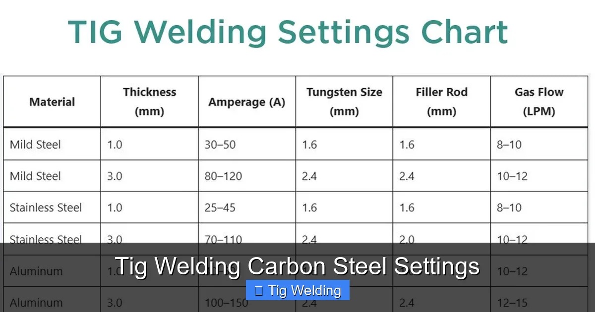
Here are some general guidelines for TIG welding carbon steel. Remember, these are starting points, and you’ll need to fine-tune them based on your specific situation.
* **18 Gauge (0.040 inches / 1mm) Steel:** 30-50 Amps
* **16 Gauge (0.059 inches / 1.5mm) Steel:** 50-75 Amps
* **14 Gauge (0.074 inches / 2mm) Steel:** 75-100 Amps
* **1/8 inch (0.125 inches / 3mm) Steel:** 100-130 Amps
* **1/4 inch (0.250 inches / 6mm) Steel:** 150-200 Amps
### Practical Tip: The Amperage Chart
Many welding machine manufacturers provide amperage charts for different materials and thicknesses. These charts are excellent resources to start with. You can also find many reliable charts online.
### Troubleshooting Amperage Issues
* **Burn-through:** If you’re burning through, your amperage is too high, or you’re holding the arc too long in one spot.
* **Lack of Fusion (Cold Lap):** If the filler metal and base metal aren’t fusing properly, your amperage is too low, or you’re not spending enough time with the arc on the joint.
## Shielding Gas: Protecting Your Weld
Shielding gas is vital for TIG welding. It creates a protective atmosphere around the arc and the molten weld pool, preventing oxidation and contamination from the air. For carbon steel, the most common and effective shielding gas is **100% Argon**.
### Why Argon for Carbon Steel?
Argon is an inert gas, meaning it doesn’t react with the molten metal. It provides excellent arc stability and good puddle control, which are essential for clean carbon steel welds. While other gases or mixtures can be used for specific applications on carbon steel (like adding a small percentage of CO2 for deeper penetration on very thick material, though this is less common and can introduce porosity if not handled correctly), pure Argon is the go-to for most TIG welding of carbon steel.
### Gas Flow Rate: The Right Amount Matters
The gas flow rate, typically measured in Cubic Feet per Hour (CFH) or Liters Per Minute (LPM), determines how much shielding gas you’re delivering.
* **Too Little Gas:** Insufficient shielding will lead to weld contamination, porosity (small holes in the weld), and a discolored or oxidized weld bead.
* **Too Much Gas:** Excessive flow can cause turbulence in the shielding gas stream, drawing in surrounding air and contaminating the weld. It also wastes gas.
### Gas Flow Rate Guidelines
* **General Rule:** A good starting point for indoor welding on flat surfaces is around **15-25 CFH (7.5-12.5 LPM)**.
* **Outdoor or Windy Conditions:** You’ll need a higher flow rate, potentially **25-35 CFH (12.5-17.5 LPM)** or more, to counteract drafts. You might also consider a welding shield.
* **Thicker Materials or Wider Joints:** Sometimes, a slightly higher flow rate can help shield a larger puddle.
* **Torch Cup Size:** Larger cups generally require higher flow rates to fill them adequately.
### Practical Tip: The Flowmeter
Your TIG welder’s gas cylinder should be equipped with a regulator and flowmeter. Ensure it’s set correctly and check it regularly.
### Troubleshooting Gas Issues
* **Porosity:** Often caused by insufficient gas flow, leaks in the gas hose or torch, or using the wrong gas.
* **Discolored Weld:** A weld that turns a rainbow of colors (blue, yellow, brown) instead of staying bright and shiny indicates oxidation due to poor shielding.
## Filler Metal: Adding Strength and Structure
Filler metal is the material you add to bridge the gap in your joint and build up the weld bead. Choosing the right filler metal is crucial for matching the base metal’s strength and properties. For carbon steel, you have several options.
### Common Filler Metals for Carbon Steel
* **ER70S-2:** A very popular all-purpose filler rod. It contains deoxidizers that help clean the puddle and produce clean welds, even on slightly contaminated surfaces. Excellent for general fabrication.
* **ER70S-3:** Similar to ER70S-2 but with slightly fewer deoxidizers. It’s also a good general-purpose rod.
* **ER70S-6:** Contains higher levels of deoxidizers (silicon and manganese) than S-2 and S-3. It’s excellent for welding steels with moderate amounts of mill scale or rust, as it helps to scavenge oxygen from the weld pool. This is often the preferred choice for general fabrication and structural work.
**”ER”** stands for Electrode Rod. The **”70″** indicates a tensile strength of 70,000 pounds per square inch (psi). The **”S”** signifies solid wire, and the numbers (2, 3, 6) refer to the specific deoxidizer content.
### Filler Metal Diameter: Matching the Job
The diameter of your filler metal rod should be matched to the thickness of the material you are welding and the amperage you are using.
* **Thin Materials (e.g., 20-26 gauge):** You might not need filler metal at all for some joints, or you’ll use a very thin rod (e.g., 0.020″ or 0.030″).
* **Medium Thickness (e.g., 1/8″ – 1/4″):** Common rod diameters are 0.030″, 0.035″, or 1/16″ (0.0625″).
* **Thick Materials (e.g., 1/4″ and up):** You might use 3/32″ (0.09375″) or 1/8″ (0.125″) rods.
### Practical Tip: Dip and Go
When TIG welding, the filler metal is fed into the leading edge of the molten puddle. Practice dipping and withdrawing the filler rod smoothly to create a consistent bead.
### Troubleshooting Filler Metal Issues
* **Rod Sticking to Tungsten:** You’re likely not feeding the filler metal into the puddle effectively, or your amperage is too low.
* **Inconsistent Bead Width:** This usually comes down to an inconsistent dipping action or movement of the torch.
## Tungsten Electrode: The Arc’s Foundation
The tungsten electrode is the non-consumable electrode that carries the welding current to create the arc. Its type, diameter, and how it’s prepared significantly impact arc stability and weld quality.
### Tungsten Types for Carbon Steel
While pure tungsten can be used, it’s generally not recommended for AC or DC welding on carbon steel. The most common types for DC welding of carbon steel are:
* **2% Thoriated (Red Band):** A very popular choice. It offers excellent arc starting, stability, and a long lifespan. Safe to use with DC current for carbon steel.
* **2% Ceriated (Orange Band):** Another excellent option for DC welding. It provides a stable arc at lower amperages and is a good alternative to thoriated. It’s also a good choice if you’re concerned about radioactive materials.
### Tungsten Diameter: Matching Amperage
The diameter of your tungsten electrode is directly related to the amperage you’ll be running.
* **Small Diameters (e.g., 0.020″ – 1/16″):** For very low amperages (under 30 Amps).
* **Medium Diameters (e.g., 3/32″):** Ideal for the majority of TIG welding on carbon steel, covering a wide amperage range (e.g., 50-200 Amps).
* **Large Diameters (e.g., 1/8″):** For higher amperages (over 200 Amps).
### Tungsten Preparation: The Pointy End
For DC welding of carbon steel, you’ll want to grind your tungsten to a **sharp, pointed tip**. This concentrates the arc, providing better control and penetration.
* **Grinding:** Use a dedicated grinder (not one used for metal cutting) with a grinding wheel specifically for tungsten. Grind longitudinally (along the length of the tungsten), not across the tip. This creates a fine, tapered point.
* **Ball-Shaped Tip:** If you accidentally melt the tip into a ball, you’ll have a very unstable arc. Re-grind it to a point.
### Practical Tip: Keep it Clean
Always use a fresh, clean tungsten electrode. Contaminated tungsten will lead to a dirty arc and poor weld quality.
### Troubleshooting Tungsten Issues
* **Arc Wander:** A dirty or improperly shaped tungsten will cause the arc to wander.
* **Electrode Melting:** If the electrode tip is melting excessively, your amperage might be too high for the tungsten diameter, or the arc is too long.
## Torch, Ground Clamp, and Foot Pedal
While not strictly “settings,” these components are crucial for executing your weld.
* **Torch:** Ensure you have the correct torch setup for your machine and are using an appropriate gas lens and cup size for the job. A gas lens helps direct the Argon more effectively.
* **Ground Clamp:** A solid connection is essential for completing the electrical circuit. Ensure the ground clamp is securely attached to clean, bare metal on the workpiece.
* **Foot Pedal:** This is your primary tool for controlling amperage. Practicing with the foot pedal is crucial for developing smooth, consistent welds. Start with a low amperage and gradually increase it as you feed in filler metal.
## Joint Preparation: The Unsung Hero
Before you even think about settings, proper joint preparation is paramount for successful TIG welding carbon steel.
### Cleaning is Non-Negotiable
* **Remove Rust, Scale, Paint, Oil, and Dirt:** Use a stainless steel wire brush or grinder to ensure the surfaces to be welded are perfectly clean. Any contaminants will end up in your weld, causing defects.
* **Degrease:** Use a degreaser or acetone to remove any oily residues.
### Joint Design Matters
* **Butt Joints:** For thinner materials, a simple square edge joint might suffice. For thicker materials, beveling the edges (creating a V-groove) allows for full penetration.
* **Lap Joints:** Overlap the two pieces of metal by at least the thickness of the thinner material.
* **Corner Joints:** Can be made with square edges or by beveling.
### Fit-Up
Ensure your pieces fit together snugly. Gaps can be difficult to bridge, especially on thinner materials.
## Putting It All Together: A Step-by-Step Example
Let’s say you’re TIG welding two pieces of 1/8″ (3mm) carbon steel together in a butt joint, flat position.
1. **Prepare the Joint:** Clean both pieces thoroughly with a stainless steel wire brush and degreaser. Ensure the edges are square and flush.
2. **Set Up Your Welder:**
* **Amperage:** Start around **110-120 Amps**.
* **Shielding Gas:** Set your flowmeter to **20 CFH (10 LPM)** of 100% Argon.
* **Tungsten:** Use a 3/32″ 2% Thoriated or Ceriated tungsten, ground to a sharp point.
* **Filler Metal:** Select a 1/16″ ER70S-6 filler rod.
3. **Torch Setup:** Use a medium-sized cup (e.g., #6 or #7) and a gas lens for good shielding.
4. **Tack Welds:** Place a few tack welds along the joint to hold the pieces in place. Ensure they penetrate properly.
5. **Begin Welding:**
* Start your arc with the foot pedal.
* Slightly increase the amperage to establish a puddle.
* Begin feeding the filler rod into the leading edge of the puddle.
* Move the torch with a steady motion, maintaining a consistent arc length and travel speed. Dip and withdraw the filler rod consistently.
* As you move, gradually increase the foot pedal pressure if needed to maintain the puddle size and penetration.
6. **Finishing the Weld:** As you reach the end, ease off the foot pedal to taper the bead and avoid crater cracks. You can also add a bit more filler material to fill the crater before extinguishing the arc.
7. **Post-Weld:** Allow the weld to cool slightly before moving. You’ll likely see a bright, clean weld bead with minimal discoloration if your settings and technique were correct.
## Advanced Tips for Carbon Steel TIG Welding
* **Foot Pedal Control:** Practice smooth, controlled movements with your foot pedal. This is where you truly master heat management.
* **Arc Length:** Aim for a consistent, short arc length. A longer arc can draw in air and create a weaker, dirtier weld.
* **Torch Angle:** A slight torch angle (around 10-15 degrees) in the direction of travel often helps with puddle control and penetration.
* **Travel Speed:** Find a speed that allows for consistent puddle formation and filler metal addition. Too fast, and you’ll have poor fusion; too slow, and you’ll overheat the metal.
* **Pulse TIG:** For very thin materials or when precise heat control is critical, consider using the pulse feature on your TIG welder. This cycles the amperage between a high and low setting, helping to control heat input and bead appearance.
## Conclusion
Mastering TIG welding settings for carbon steel is a journey of understanding and practice. By paying close attention to amperage, shielding gas, filler metal, and tungsten selection, you lay the foundation for strong, clean, and beautiful welds. Remember that these are starting points, and the best settings will always be found through careful observation and practice on your specific equipment and materials. Don’t be afraid to experiment, make adjustments, and learn from each weld. With dedication and the knowledge gained from this guide, you’ll be well on your way to TIG welding carbon steel like a pro. Happy welding!
Key Takeaways
- Understanding Amperage: The correct amperage is crucial for proper heat input, preventing burn-through or lack of fusion.
- Gas Selection and Flow Rate: Pure Argon is standard for carbon steel TIG, with flow rates adjusted based on shielding needs and environmental factors.
- Filler Metal Choice: Selecting the right filler metal diameter and type is essential for matching the base metal and achieving desired mechanical properties.
- Tungsten Electrode Selection: Thoriated or Ceriated tungsten are common choices, with electrode diameter influencing amperage capacity and arc stability.
- Joint Preparation is Key: Cleanliness and proper joint design significantly impact weld quality and ease of execution.
- Foot Pedal Control: Mastering the foot pedal allows for precise heat management, crucial for consistent bead appearance and penetration.
