

This guide explains how to use a MIG welding gas flow rate chart to achieve optimal shielding gas coverage. You’ll learn the correct flow rates for different materials, troubleshoot common issues, and improve weld quality with simple adjustments.
Key Takeaways
- Correct gas flow prevents porosity: Too little gas leads to contamination; too much causes turbulence and wasted gas.
- Standard flow rates range from 15–25 CFH: Most MIG welding jobs work best within this range, depending on material and environment.
- Use a flow meter for accuracy: Always attach a flow meter to your regulator to monitor and adjust gas output precisely.
- Environmental factors matter: Wind, drafts, or high humidity can disrupt gas shielding and require higher flow rates.
- Material thickness and joint type affect settings: Thicker materials or open joints may need increased gas flow for full protection.
- Common shielding gases include 75/25 Argon/CO2: This mix is ideal for mild steel and offers a good balance of penetration and stability.
- Always test settings on scrap metal: Fine-tune your gas flow before welding on final pieces to avoid defects.
What Is a MIG Welding Gas Flow Rate Chart?
A MIG welding gas flow rate chart is a reference tool that helps welders determine the correct volume of shielding gas to use during the welding process. Shielding gas protects the molten weld pool from reacting with oxygen, nitrogen, and other elements in the air. Without proper gas coverage, welds can become porous, brittle, or discolored.
The chart typically lists recommended flow rates in cubic feet per hour (CFH) based on factors like material type, wire diameter, joint design, and environmental conditions. Using this chart ensures consistent, high-quality welds and reduces the risk of defects.
Why Gas Flow Rate Matters in MIG Welding
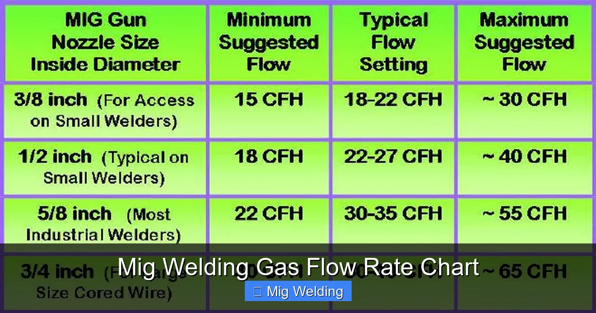
Visual guide about Mig Welding Gas Flow Rate Chart
Image source: netwelding.com
Shielding gas is the invisible hero of MIG welding. It forms a protective bubble around the arc and weld pool, preventing atmospheric contamination. If the gas flow is too low, air can enter the weld zone, causing porosity—tiny holes that weaken the joint. On the other hand, too high a flow rate can create turbulence, drawing air into the shielding zone and wasting expensive gas.
Getting the flow rate right improves weld appearance, strength, and efficiency. It also reduces spatter and post-weld cleanup. Whether you’re welding thin sheet metal or thick steel plates, the right gas flow is essential.
Understanding Shielding Gases and Their Uses
Visual guide about Mig Welding Gas Flow Rate Chart
Image source: weldguru.com
Before diving into flow rates, it’s important to know which gases are commonly used in MIG welding and why.
Common Shielding Gases
- 75% Argon / 25% CO2: The most popular mix for mild steel. It provides smooth arc stability, good penetration, and minimal spatter.
- 100% CO2: Offers deep penetration but more spatter. Often used in industrial settings where cost is a concern.
- 90% Argon / 10% CO2: A cleaner alternative for thinner materials, reducing burn-through and spatter.
- Argon/Helium mixes: Used for aluminum and non-ferrous metals, providing better heat input and arc characteristics.
Each gas behaves differently, so your flow rate may need adjustment based on the gas type. For example, pure CO2 may require slightly higher flow rates than argon blends due to its lower density.
How to Use a MIG Welding Gas Flow Rate Chart
Using a gas flow rate chart is simple once you understand the variables involved. Here’s a step-by-step guide to help you get started.
Step 1: Identify Your Material and Thickness
Different materials require different shielding approaches. Mild steel, stainless steel, and aluminum each have unique needs. Thicker materials generally need more gas to ensure full coverage, especially in open joints or fillet welds.
For example:
– 18-gauge mild steel: 15–18 CFH
– 1/4-inch mild steel: 20–25 CFH
– Aluminum (1/8-inch): 20–25 CFH (with argon-helium mix)
Step 2: Check Your Wire Diameter
Thicker welding wires (like 0.045″) produce larger weld pools and may need slightly higher gas flow to protect the entire area. Thinner wires (0.023″ or 0.030″) typically work well with lower flow rates.
Step 3: Consider Joint Type and Welding Position
Butt joints, lap joints, and T-joints all affect gas coverage. Open joints or gaps can allow gas to escape, requiring higher flow. Vertical or overhead welding may also need increased flow to maintain shielding as the weld pool moves.
Step 4: Account for Environmental Conditions
Welding outdoors or in drafty workshops? Wind can blow away shielding gas, so increase flow by 3–5 CFH. High humidity can also affect arc stability, so ensure your gas is dry and your flow is consistent.
Step 5: Set the Flow Rate Using a Flow Meter
Never guess the gas flow. Always use a flow meter attached to your regulator. Turn on the gas and adjust the knob until the float reaches the recommended CFH on your chart. Let the system stabilize for 10–15 seconds before welding.
Recommended Gas Flow Rates by Application
Here’s a practical MIG welding gas flow rate chart to guide your setup:
| Material | Thickness | Wire Diameter | Shielding Gas | Recommended Flow Rate (CFH) |
|---|---|---|---|---|
| Mild Steel | 24–20 gauge | 0.023″–0.030″ | 75/25 Ar/CO2 | 15–18 |
| Mild Steel | 18–14 gauge | 0.030″–0.035″ | 75/25 Ar/CO2 | 18–22 |
| Mild Steel | 1/8″–1/4″ | 0.035″–0.045″ | 75/25 Ar/CO2 or 100% CO2 | 20–25 |
| Stainless Steel | 16–12 gauge | 0.030″–0.035″ | 98% Ar / 2% O2 or Tri-mix | 18–22 |
| Aluminum | 1/8″–1/4″ | 0.035″–0.045″ | 100% Argon or Ar/He | 20–25 |
Note: These are general guidelines. Always test on scrap material first.
Practical Tips for Setting Gas Flow
Getting the perfect weld isn’t just about numbers—it’s about technique and awareness.
Use a Gas Lens or Nozzle Extension
These accessories improve gas coverage by directing flow more evenly around the weld. They’re especially helpful in tight spaces or when welding aluminum.
Check for Leaks
A leaky connection can reduce gas pressure and flow. Use soapy water to check fittings, hoses, and the regulator. Bubbles indicate a leak that needs tightening or replacement.
Pre-Flow and Post-Flow Settings
Many MIG welders have pre-flow (gas starts before arc) and post-flow (gas continues after arc) settings. Set pre-flow to 0.1–0.3 seconds and post-flow to 0.5–1.5 seconds to protect the weld start and crater.
Monitor Gas Usage
Keep an eye on your gas tank pressure. A full tank should read around 2000–2200 PSI. When it drops below 500 PSI, it’s time to replace it—low pressure can cause inconsistent flow.
Troubleshooting Common Gas Flow Issues
Even with the right chart, problems can arise. Here’s how to fix them.
Porosity in the Weld
Symptoms: Small holes or bubbles in the weld bead.
Causes: Low gas flow, wind, dirty metal, or leaks.
Solution: Increase flow rate, shield the weld area, clean the metal, and check for leaks.
Excessive Spatter
Symptoms: Chunks of molten metal sticking to the workpiece.
Causes: High voltage, wrong wire feed speed, or too much gas causing turbulence.
Solution: Adjust voltage and wire speed. Reduce gas flow slightly if it’s above 25 CFH.
Unstable Arc or Arc Blow
Symptoms: Arc wanders or extinguishes unexpectedly.
Causes: Poor grounding, magnetic fields, or insufficient gas coverage.
Solution: Ensure good ground connection, reposition ground clamp, and verify gas flow.
Discolored or Oxidized Welds
Symptoms: Blue, black, or rainbow-colored streaks on the weld.
Causes: Air contamination due to low flow or post-flow ending too soon.
Solution: Increase post-flow time and ensure adequate gas coverage during cooling.
Final Tips for Consistent Results
– Always use clean, dry gas cylinders. Moisture in the gas can cause porosity.
– Store gas cylinders upright and secure them to prevent tipping.
– Replace worn nozzles and contact tips—they can disrupt gas flow.
– Keep a log of your settings for different projects to build experience.
– When in doubt, start low and increase gradually. It’s easier to add gas than to fix a turbulent weld.
Conclusion
Using a MIG welding gas flow rate chart is a simple yet powerful way to improve your welding quality. By matching the right flow rate to your material, wire, and environment, you’ll achieve cleaner, stronger, and more consistent welds. Remember, the chart is a starting point—fine-tuning based on real-world conditions is key. With practice and attention to detail, you’ll master gas flow and take your MIG welding to the next level.