

This guide explains how to use a MIG welding gas flow rate chart to achieve clean, strong welds. You’ll learn ideal flow rates for different materials, gases, and conditions, plus tips to avoid common mistakes.
Key Takeaways
- Optimal gas flow is essential: Too little causes porosity; too much wastes gas and disrupts shielding.
- Standard flow rate range: Most MIG welding uses 20–30 CFH (cubic feet per hour) of shielding gas.
- Material and gas type matter: Steel, aluminum, and stainless steel require different gas mixes and flow rates.
- Environmental factors count: Wind, drafts, or high humidity may require adjustments to your flow rate.
- Use a regulator and flowmeter: These tools ensure accurate gas delivery and help maintain consistency.
- Refer to a MIG welding gas flow rate chart: It simplifies setup and improves weld quality across projects.
- Test and adjust: Always do a test weld and fine-tune flow based on bead appearance and spatter levels.
What Is a MIG Welding Gas Flow Rate Chart?
A MIG welding gas flow rate chart is a reference tool that shows the recommended cubic feet per hour (CFH) of shielding gas to use based on your welding setup. It considers factors like material type, wire diameter, gas mixture, and joint design. Using the right flow rate ensures the weld pool is protected from air, which can cause defects like porosity, oxidation, and weak joints.
Shielding gas plays a critical role in MIG welding. It creates a protective envelope around the arc and molten metal, preventing contamination. Without proper gas coverage, your welds may look good on the surface but fail under stress. That’s why understanding and applying the correct flow rate is so important—even small changes can make a big difference in weld quality.
This guide will walk you through how to read and use a MIG welding gas flow rate chart, choose the right gas, set up your equipment, and troubleshoot common issues. Whether you’re a beginner or an experienced welder, mastering gas flow will help you produce cleaner, stronger, and more consistent welds.
Why Gas Flow Rate Matters in MIG Welding
Visual guide about Mig Welding Gas Flow Rate Chart
Image source: fitupgear.com
Shielding gas protects the weld pool from oxygen, nitrogen, and moisture in the air. When these elements mix with molten metal, they create tiny bubbles or cracks—called porosity—that weaken the weld. Too little gas flow won’t provide enough coverage, especially in drafty areas. Too much gas can cause turbulence, pulling air into the shielding zone and creating the same problems.
Using the correct flow rate also improves arc stability, reduces spatter, and helps control the weld bead shape. It can even extend the life of your contact tips and nozzles by reducing carbon buildup. In short, proper gas flow is one of the most overlooked yet impactful variables in MIG welding.
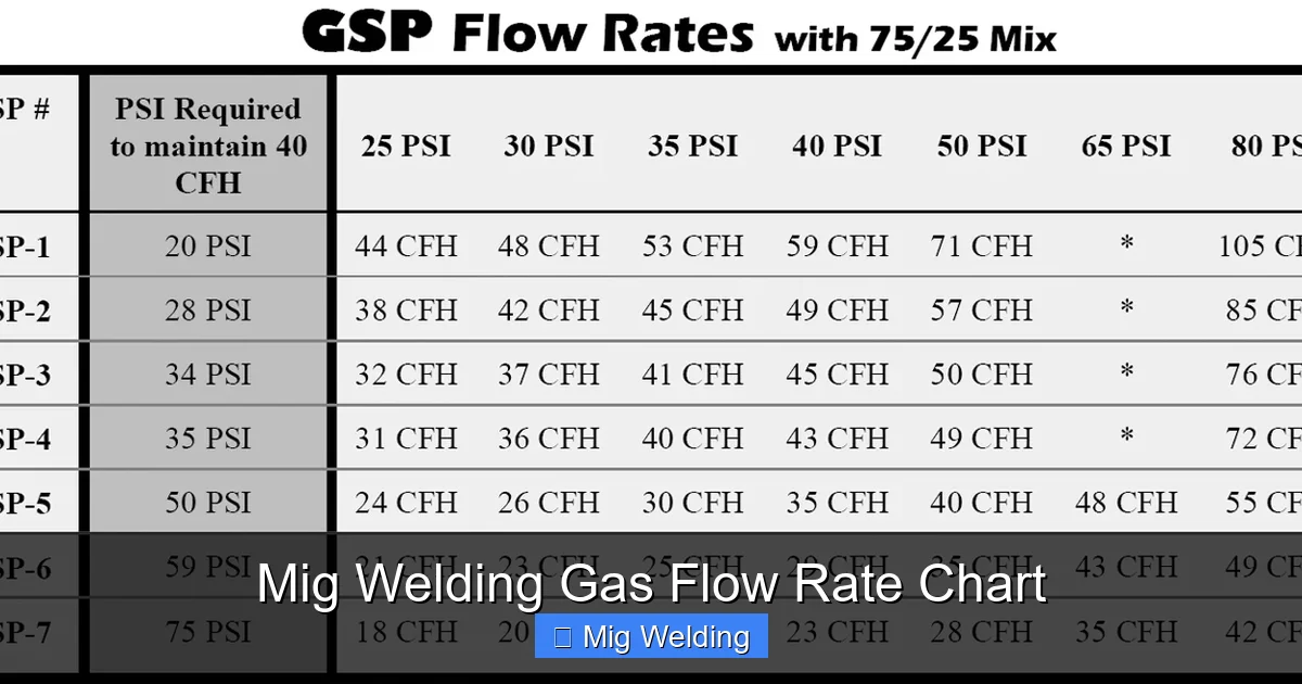
Understanding the Standard Flow Rate Range
Visual guide about Mig Welding Gas Flow Rate Chart
Image source: i.ytimg.com
Most MIG welding applications use a gas flow rate between 20 and 30 CFH. This range works well for indoor welding with minimal drafts and standard wire diameters (0.030″ to 0.045″). However, this isn’t a one-size-fits-all number. You’ll need to adjust based on your specific setup.
For example, welding thin materials or using smaller wires (like 0.023″) might only need 18–22 CFH. Thicker materials or larger wires may require 25–30 CFH. If you’re welding outdoors or in a windy shop, you might need to increase the flow slightly—but be careful not to go overboard.
How to Read a MIG Welding Gas Flow Rate Chart
A typical MIG welding gas flow rate chart is organized by material type and gas mixture. Here’s how to use one:
Step 1: Identify Your Base Material
Determine whether you’re welding mild steel, stainless steel, or aluminum. Each material has different requirements.
Step 2: Choose Your Shielding Gas
Common gas mixes include:
- 75% Argon / 25% CO₂ (C25) for mild steel
- 90% Argon / 10% CO₂ for smoother welds on steel
- 100% CO₂ for deeper penetration (but more spatter)
- 98% Argon / 2% Oxygen for stainless steel
- 100% Argon for aluminum
Step 3: Match Wire Diameter and Joint Type
Thicker wires and open joints may need slightly higher flow rates. For example, a 0.045″ wire on a butt joint might use 25 CFH, while a 0.030″ wire on a lap joint could use 20 CFH.
Step 4: Adjust for Environment
Indoor welding in a controlled environment? Stick to the chart. Outdoor or drafty conditions? Add 2–5 CFH to compensate for air movement.
Recommended Gas Flow Rates by Material and Gas
Below is a practical breakdown of common setups:
Mild Steel with C25 (75/25 Argon/CO₂)
- 0.023″ wire: 18–22 CFH
- 0.030″ wire: 20–25 CFH
- 0.035″ wire: 22–27 CFH
- 0.045″ wire: 25–30 CFH
C25 is the most popular mix for mild steel because it offers good arc stability, low spatter, and decent penetration.
Mild Steel with 100% CO₂
- 0.030″ wire: 25–30 CFH
- 0.035″ wire: 28–32 CFH
- 0.045″ wire: 30–35 CFH
CO₂ provides deeper penetration but increases spatter and requires higher flow rates. Use it when strength is more important than appearance.
Stainless Steel with 98/2 Argon/Oxygen
- 0.030″ wire: 20–25 CFH
- 0.035″ wire: 22–27 CFH
This mix prevents oxidation and maintains corrosion resistance. Avoid CO₂ with stainless steel—it can cause carbide precipitation.
Aluminum with 100% Argon
- 0.035″ wire: 20–25 CFH
- 0.045″ wire: 25–30 CFH
Aluminum requires clean, consistent gas coverage. Use a push technique and ensure your gas nozzle is large enough to cover the weld area.
How to Set Up Your Gas Flow Correctly
Follow these steps to dial in the perfect flow rate:
Step 1: Install a Flowmeter
Use a high-quality flowmeter with your gas regulator. This lets you measure CFH accurately. Avoid cheap gauges—they often drift over time.
Step 2: Set the Regulator Pressure
Most MIG welders don’t need high pressure. Set the regulator to 30–50 PSI. The flowmeter will control the actual gas flow.
Step 3: Adjust the Flow Rate
Turn the flowmeter knob until the ball reaches the recommended CFH. For example, set it to 25 CFH for a 0.035″ wire on mild steel with C25.
Step 4: Check for Leaks
Spray soapy water on all connections. Bubbles mean a leak. Tighten fittings or replace damaged hoses.
Step 5: Allow Gas to Flow Before Welding
Turn on the gas 2–3 seconds before striking an arc. This purges air from the line and ensures full shielding from the start.
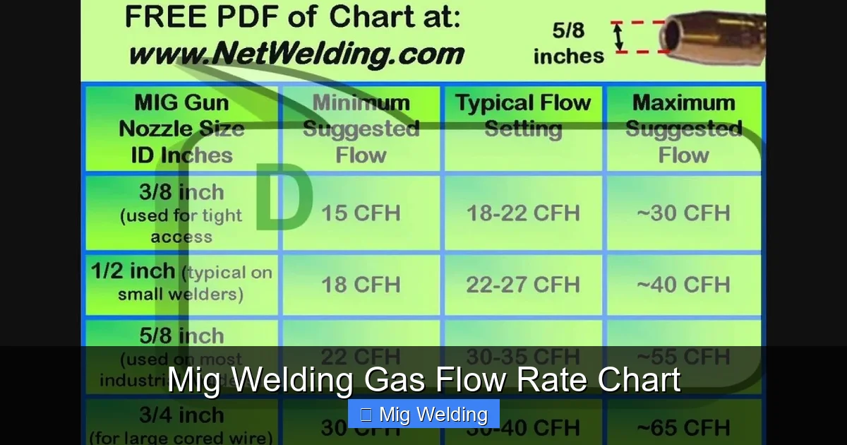
Practical Tips for Better Gas Coverage
Even with the right flow rate, poor technique can ruin your welds. Here are some pro tips:
- Use a larger gas nozzle: A #6 or #7 nozzle provides better coverage than smaller ones.
- Keep the nozzle close to the workpiece: ½ to ¾ inch is ideal. Too far reduces effectiveness.
- Avoid cross drafts: Use welding screens or curtains to block air movement.
- Clean your material: Oil, rust, and paint can trap moisture and cause porosity.
- Use a gas lens (for aluminum): It improves gas distribution and allows longer stick-out.
Troubleshooting Common Gas Flow Issues
Even with a chart, problems can happen. Here’s how to fix them:
Porosity in the Weld
- Cause: Insufficient gas flow, leaks, or drafts.
- Solution: Increase flow by 2–3 CFH, check for leaks, and shield the weld area.
Excessive Spatter
- Cause: Too much gas flow or incorrect voltage/wire speed.
- Solution: Reduce flow slightly and fine-tune your machine settings.
Erratic Arc or Arc Blow
- Cause: Turbulent gas flow or magnetic interference.
- Solution: Use a gas diffuser or switch to a different gas mix.
Gas Not Turning On
- Cause: Closed valve, empty cylinder, or faulty solenoid.
- Solution: Check the tank valve, replace the cylinder, or test the solenoid.
When to Adjust the Flow Rate
Don’t stick to the chart blindly. Adjust your flow rate when:
- Welding outdoors or in windy conditions
- Using a long gas hose (over 25 feet)
- Welding in tight spaces where gas can’t escape
- Switching to a different wire type or diameter
- Noticing changes in weld appearance or spatter
Always do a test weld on scrap metal. Look for a smooth, shiny bead with minimal spatter. If the bead is dull or porous, adjust the flow and try again.
Conclusion
Using a MIG welding gas flow rate chart is one of the simplest ways to improve your weld quality. By matching the right flow rate to your material, gas, and setup, you’ll reduce defects, save money on gas, and produce stronger, cleaner welds. Remember, the standard range is 20–30 CFH, but always fine-tune based on real-world conditions. With practice and attention to detail, you’ll master gas flow and take your MIG welding to the next level.