

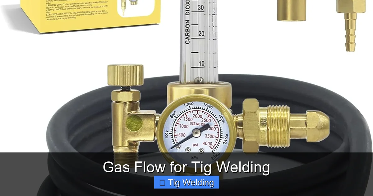
Proper gas flow is a cornerstone of successful TIG welding. This guide demystifies the process, covering everything from understanding the role of shielding gas to selecting the correct gas and flow rate for your specific application. Learn how to achieve strong, clean, and aesthetically pleasing TIG welds by mastering gas flow.
Gas Flow for Tig Welding
Key Takeaways
- Understanding Shielding Gas: The primary function of gas flow in TIG welding is to create a protective shield around the molten weld pool, preventing atmospheric contamination that leads to porosity and weak welds.
- Choosing the Right Gas: Argon is the most common and versatile shielding gas for TIG welding, especially for aluminum and mild steel. Other gases like Helium, CO2, and gas mixtures offer specific benefits for different metals and applications.
- Flow Rate Calculation and Setting: The ideal gas flow rate depends on factors like nozzle size, amperage, and environmental conditions. Generally, a flow rate between 15-25 CFH (Cubic Feet per Hour) is a good starting point.
- Pre-flow and Post-flow Importance: Pre-flow purges the torch and weld area of air before the arc starts, while post-flow maintains the shield after the arc stops, preventing oxidation and contamination.
- Troubleshooting Common Gas Flow Issues: Problems like porosity, poor penetration, and discoloration often stem from incorrect gas flow. Adjusting flow rates, checking for leaks, and ensuring proper torch setup can resolve these issues.
- Nozzle Size Matters: Larger nozzles generally require higher flow rates to adequately cover the weld pool. Consistent use of the correct nozzle size is crucial for predictable gas coverage.
Introduction: The Unsung Hero of TIG Welding
TIG (Tungsten Inert Gas) welding, also known as GTAW (Gas Tungsten Arc Welding), is renowned for its precision, control, and ability to produce incredibly clean and strong welds. While the tungsten electrode, filler material, and arc control are often highlighted, there’s a critical element that often works behind the scenes but is absolutely vital for success: gas flow. Without the correct shielding gas flow, your TIG welds will be prone to contamination, leading to porosity, weak joints, and an unattractive appearance. This guide will equip you with the knowledge to master gas flow for TIG welding, ensuring you achieve beautiful and robust welds every time.
In this comprehensive guide, you will learn:
- The fundamental role of shielding gas in TIG welding.
- How to choose the most appropriate shielding gas for various metals.
- The science behind setting the correct gas flow rate.
- Step-by-step instructions on how to set and manage your gas flow.
- Tips for optimizing gas coverage and preventing common problems.
- How to troubleshoot issues related to gas flow.
By the end of this guide, you’ll have a solid understanding of gas flow’s importance and the practical skills to implement it effectively in your TIG welding projects.
Understanding the Role of Shielding Gas
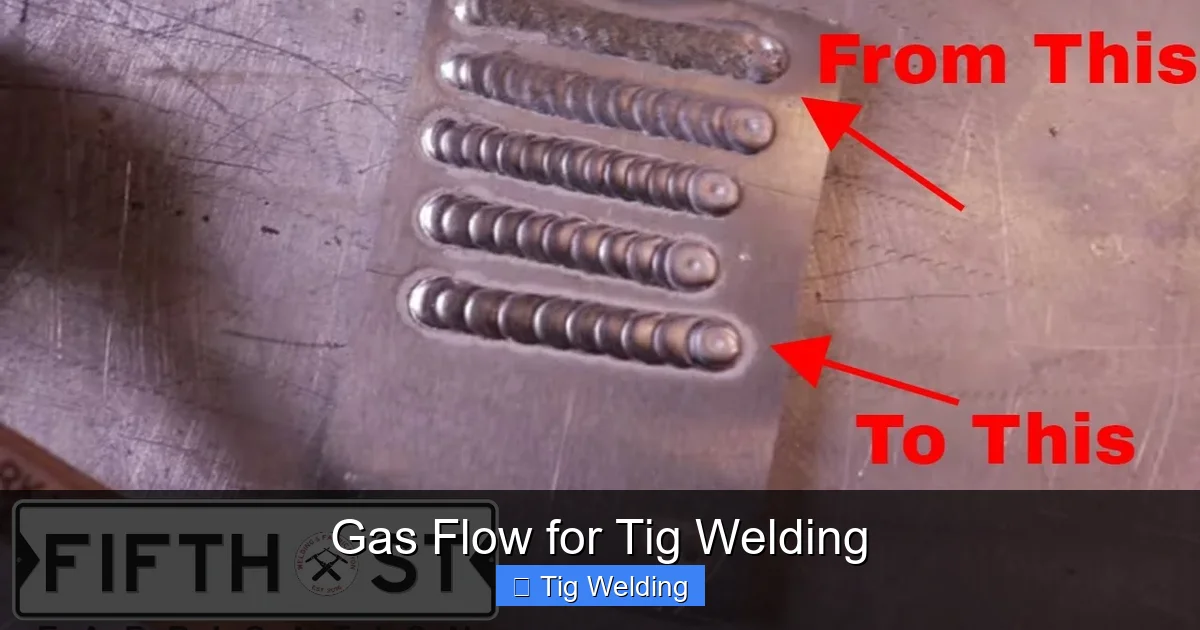
At its core, TIG welding creates a weld pool by directing an electric arc between a non-consumable tungsten electrode and the workpiece. The extreme heat of the arc melts the base metal and any filler material you add. However, the air around this molten metal is a problem. Air contains oxygen and nitrogen, both of which are highly reactive and will combine with the molten metal, forming oxides and nitrides. These inclusions, known as porosity, severely weaken the weld and can lead to premature failure.
Visual guide about Gas Flow for Tig Welding
Image source: i.ytimg.com
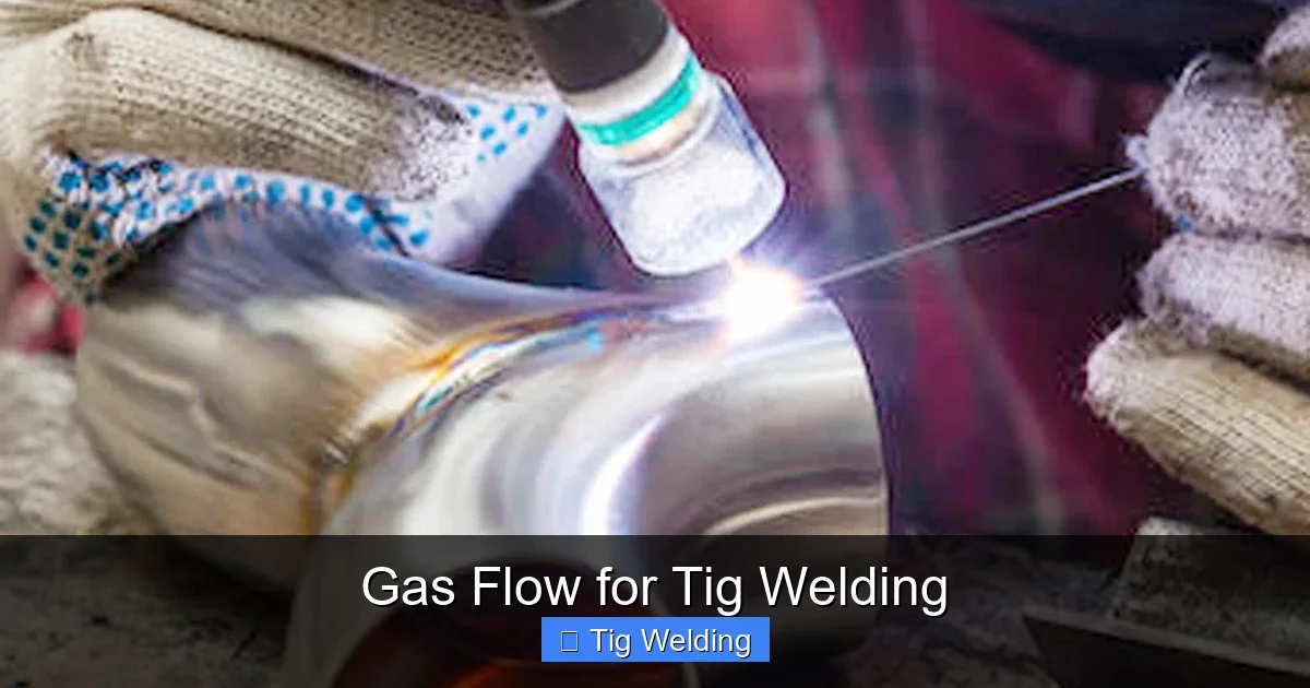
This is where the shielding gas comes in. Delivered through the TIG torch’s cup (or nozzle), the inert gas flows to create a protective bubble around the tungsten electrode, the molten weld pool, and the hot filler metal. This bubble displaces the surrounding atmosphere, preventing oxygen and nitrogen from reaching and contaminating the weld.
Think of it like this: you’re trying to create a pristine, clean environment for your molten metal. The shielding gas is your invisible force field, keeping all the contaminants out.
The Importance of Inert Gases
The gases used in TIG welding are typically inert. This means they are very unreactive. They won’t chemically combine with the tungsten electrode, the molten metal, or the surrounding air under normal welding conditions. This inertness is crucial because we only want the gas to provide a physical barrier, not to introduce any chemical changes.
Key Functions of Shielding Gas:
- Preventing Oxidation: Shields the molten weld pool from atmospheric oxygen, which causes brittle oxides.
- Preventing Contamination: Stops nitrogen and other atmospheric gases from entering the weld, which can form detrimental nitrides.
- Stabilizing the Arc: Certain gases help to create a more stable and consistent arc, leading to better penetration and bead profile.
- Cooling: Some gases can help to dissipate heat, influencing the weld puddle’s fluidity and solidification.
Choosing the Right Shielding Gas
The choice of shielding gas is paramount and depends heavily on the type of metal you are welding, the thickness of the material, and the desired weld characteristics. While one gas might be perfect for aluminum, it could be detrimental for stainless steel.
Visual guide about Gas Flow for Tig Welding
Image source: garagewelding.com
1. Pure Argon (Ar)
When to Use: Argon is the most widely used and versatile shielding gas for TIG welding. It’s the go-to choice for welding aluminum, magnesium, titanium, and copper alloys. It’s also commonly used for mild steel and stainless steel, especially for thinner materials or when a clean, bright weld bead is desired.
Why it Works: Argon is denser than air, meaning it flows well and effectively blankets the weld pool. It produces a stable arc and offers good cleaning action, particularly important for aluminum, which has a tenacious oxide layer.
2. Pure Helium (He)
When to Use: Helium is often used in combination with argon or on its own for thicker sections of aluminum, copper alloys, and stainless steel. It’s also preferred for high-speed welding applications.
Why it Works: Helium has a higher thermal conductivity than argon. This means it transfers more heat to the weld pool, resulting in deeper penetration and a wider bead. This increased heat can be beneficial for welding thicker materials or when faster travel speeds are needed. However, helium is less dense than argon, so it doesn’t blanket the weld pool as effectively, making it more susceptible to drafts. Higher flow rates are also typically required.
3. Argon-Helium Mixtures (Ar/He)
When to Use: These mixtures combine the benefits of both gases. For example, a 75% Argon / 25% Helium mix provides better heat input than pure argon but with more stable arc characteristics than pure helium. They are excellent for welding thicker aluminum, stainless steel, and exotic metals where increased penetration and faster welding speeds are beneficial.
Why it Works: The argon provides arc stability and good coverage, while the helium adds heat for deeper penetration. The ratio can be adjusted to fine-tune the welding characteristics.
4. Carbon Dioxide (CO2)
When to Use: Pure CO2 is rarely used for TIG welding. It’s highly reactive and tends to create a less stable arc, significant spatter, and a rough weld bead. It’s more commonly found in MIG welding for steel.
5. Argon-CO2 Mixtures (Ar/CO2)
When to Use: These mixtures are sometimes used for TIG welding carbon steel. The CO2 acts as an oxidizing agent, which can help reduce surface tension and improve bead wetting. However, they produce a rougher bead and are less clean than pure argon welds. For most applications, pure argon or argon-helium mixtures are preferred for higher quality welds.
6. Other Gases and Mixtures
For specialized applications, other gases like Hydrogen (H2) can be added to argon for TIG welding stainless steel or nickel alloys. Hydrogen acts as a reducing agent, preventing oxidation and promoting a brighter, cleaner bead. However, hydrogen can cause embrittlement in some materials, so its use requires careful consideration and expertise.
Setting the Gas Flow Rate: Finding the Sweet Spot
Setting the correct gas flow rate is crucial. Too little flow, and you won’t get adequate shielding, leading to contamination. Too much flow can actually disrupt the shielding gas envelope, pull in surrounding air, and even create turbulence that causes porosity. It’s a delicate balance.
Visual guide about Gas Flow for Tig Welding
Image source: img.banggood.com
Factors Influencing Gas Flow Rate:
- Nozzle Size: This is arguably the most significant factor. Larger cups require more gas to fill the expanded volume and provide adequate coverage.
- Amperage: Higher amperages create larger weld pools and require more shielding.
- Material Thickness: Thicker materials generally need higher heat input and thus potentially higher gas flow.
- Welding Position: Out-of-position welding might require slight adjustments to account for gas drift.
- Environmental Conditions: Drafty environments may necessitate higher flow rates or the use of draft shields.
- Gas Type: Helium, being less dense, generally requires a higher flow rate than argon to achieve the same level of coverage.
Standard Flow Rate Guidelines:
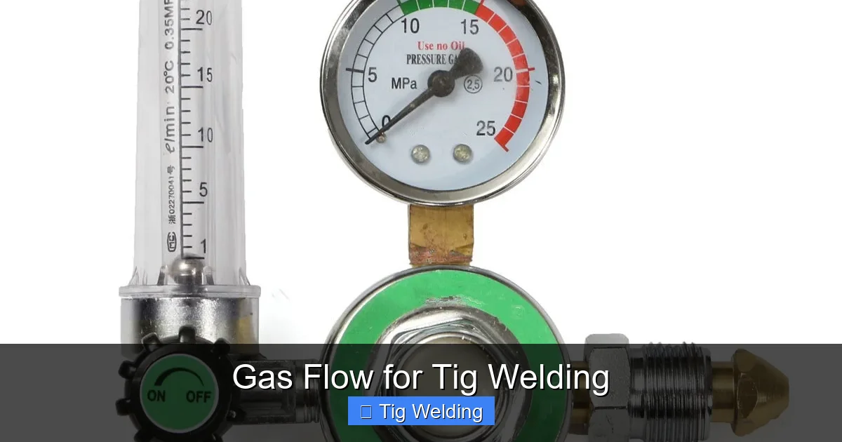
The most common unit for measuring gas flow is Cubic Feet per Hour (CFH). Your gas regulator gauge will likely display this. A good starting point for many common TIG welding scenarios:
- Small Nozzle (e.g., #5 or #6): 10-15 CFH
- Medium Nozzle (e.g., #7 or #8): 15-25 CFH
- Large Nozzle (e.g., #9 or larger): 20-30+ CFH
Important Note: These are general guidelines. Always consult your welding machine’s manual, your gas supplier’s recommendations, or a TIG welding expert for specific advice related to your equipment and application.
Step-by-Step: Setting and Managing Your Gas Flow
Setting up your gas flow involves a few key steps, from connecting the cylinder to verifying coverage.
Step 1: Connect the Gas Cylinder and Regulator
H3: Connect the Regulator
- Ensure the cylinder valve is closed.
- Gently screw the regulator onto the gas cylinder, making sure it’s hand-tight and properly aligned.
- If you have a preset regulator, it will attach directly. If you have a standard two-gauge regulator, ensure the connection is secure.
H3: Open the Cylinder Valve Slowly
- Slowly open the main cylinder valve. Listen for any hissing sounds that might indicate a leak.
- The high-pressure gauge on the regulator will show the remaining pressure in the cylinder.
Step 2: Set the Flow Rate
H3: Adjust the Regulator Valve
- Most modern regulators have a control knob or a needle valve. Turn this knob to adjust the flow rate.
- Watch the flowmeter (often a clear tube with a ball inside) or the gauge. Adjust the knob until the ball is at the desired CFH mark.
H3: Check for Leaks (Again)
- With the regulator set and a slight flow, check all connections (cylinder to regulator, regulator to hose) for bubbles if using a soap solution, or listen for hissing. A small leak can waste a lot of gas and compromise your shielding.
Step 3: Connect to the TIG Torch and Set Pre-flow/Post-flow
Your TIG welding machine has controls for gas flow. These typically include:
- Pre-flow Time: This is the duration the gas flows *before* the arc starts. It’s essential to purge the torch assembly and the weld area of any surrounding air. A pre-flow of 0.5 to 1.0 seconds is usually sufficient.
- Flow Rate (Main Flow): This is the flow rate set on your regulator.
- Post-flow Time: This is the duration the gas continues to flow *after* the arc is extinguished. This is critical for preventing oxidation of the hot weld bead and the tungsten electrode as they cool. A post-flow of 5 to 15 seconds is common, depending on the amperage and material.
Consult your TIG machine’s manual for specific instructions on setting pre-flow and post-flow times. These are usually adjustable via knobs or digital settings on the machine’s front panel.
Step 4: Test the Gas Coverage
H3: The “Finger Test” (Carefully!)
- While not a precise measurement, you can get a feel for the gas flow. With the welding machine on, torch in hand, and gas flowing (arc not struck), gently hold your finger near the opening of the gas cup. You should feel a steady, gentle flow of gas.
H3: Visual Inspection of the Weld
- The best indicator is the weld itself. After making a test weld, inspect the weld bead.
- Good Coverage: A clean, bright, and slightly convex weld bead with minimal discoloration around it.
- Poor Coverage (Too Little Gas): Discoloration (blues, browns, purples, or even a dull grey/black) on the weld and the surrounding area. Porosity (small pinholes) within the weld.
- Poor Coverage (Too Much Gas/Turbulence): Porosity can still occur if the gas flow is too high and creates turbulence, drawing air into the shield. The tungsten might also appear “blown back.”
Step 5: Fine-Tuning Your Flow Rate
Based on your test welds and visual inspection, you may need to adjust your flow rate:
- If you see discoloration or porosity: Increase the flow rate slightly, or increase the post-flow time. Ensure you are using the correct nozzle size for the job.
- If the weld bead is excessively wide or the tungsten appears to be blown back: Decrease the flow rate slightly, or shorten the post-flow time.
Practical Tip: Always perform test welds on scrap material of the same type and thickness as your project. This allows you to dial in your settings without compromising your actual work.
Troubleshooting Common Gas Flow Issues
Even with careful setup, problems can arise. Here’s how to tackle them:
Problem: Porosity in the Weld
Causes:
- Insufficient shielding gas flow.
- Drafts or wind affecting the gas shield.
- Excessive gas flow causing turbulence.
- Dirty base metal or filler rod.
- Incorrect pre-flow or post-flow settings.
- Leaky gas connections.
Solutions:
- Increase gas flow rate gradually.
- Use a draft shield or weld in a less windy area.
- Check and potentially lower the gas flow rate.
- Thoroughly clean the base metal and filler rod.
- Ensure proper pre-flow and post-flow times are set.
- Inspect and fix any gas leaks.
Problem: Poor Penetration
Causes:
- Insufficient gas flow can sometimes affect arc stability.
- Using the wrong gas (e.g., pure helium on very thin material might cause it to blow through too quickly, but insufficient heat can also cause poor penetration).
- Low amperage.
Solutions:
- While not directly a gas flow issue, ensure arc stability is good.
- Consider using pure argon for better arc control on many materials if penetration is too shallow.
- Increase amperage.
Problem: Discoloration (Oxidation)
Causes:
- Inadequate shielding gas.
- Insufficient post-flow time.
- Drafts.
Solutions:
- Increase gas flow rate.
- Increase post-flow time.
- Use a draft shield or weld in a protected area.
Problem: Tungsten Contamination
Causes:
- Arc length too long.
- Filler rod touching the tungsten.
- Insufficient gas flow or turbulence causing the arc to be blown back onto the tungsten.
Solutions:
- Maintain a consistent, short arc length.
- Keep the filler rod from touching the tungsten electrode.
- Ensure adequate and stable gas flow.
Problem: Gas is Flowing, But I Don’t Feel Anything
Causes:
- Regulator or hose leak.
- Torch valve stuck open.
- Internal blockage in the torch or gas line.
Solutions:
- Thoroughly check all connections for leaks.
- Ensure the torch valve (if present) is closing properly.
- Consult your TIG machine manual or a technician if you suspect an internal blockage.
Practical Tips for Optimal Gas Flow
- Use the Correct Nozzle Size: This is crucial. A #5 nozzle on a high-amperage weld will never have enough coverage, no matter how high you set the flow. Conversely, a #10 nozzle with only 10 CFH will also be inadequate. Stick to the recommendations for your amperage and application.
- Keep Your Torch Clean: Debris or spatter inside the gas cup can disrupt gas flow. Clean it regularly.
- Be Mindful of Drafts: Even a slight breeze can blow your shielding gas away. If you’re welding outdoors or in a drafty workshop, use a portable draft shield or consider welding at a different time/location.
- Inspect Your Gas Hose: Ensure the hose from the regulator to the machine is not kinked, cracked, or damaged.
- Know Your Gas: Always double-check that you have the correct gas cylinder connected. Accidentally using the wrong gas can be catastrophic for your weld quality.
- Listen to Your Arc: An experienced welder can often “hear” when the gas flow is incorrect. A sputtering or unstable arc can be a sign of gas issues.
Conclusion: The Foundation of Quality TIG Welds
Mastering gas flow is not an optional extra in TIG welding; it’s a fundamental requirement for achieving strong, clean, and aesthetically pleasing results. By understanding the role of shielding gas, selecting the appropriate gas for your material, and meticulously setting and managing your flow rates, you lay the groundwork for success.
Remember that practice and observation are key. Pay attention to your weld appearance, listen to your arc, and don’t be afraid to make small adjustments to your gas settings during test welds. With consistent effort and attention to detail, you’ll find that proper gas flow becomes second nature, elevating your TIG welding skills to new heights.
