

This guide demystifies argon pressure for TIG welding, a crucial factor for achieving strong, clean, and visually appealing welds. We’ll cover how to select the right flow rate for different metals, joint types, and welding conditions. Understanding and controlling your argon pressure ensures proper shielding gas coverage, preventing contamination and ensuring high-quality TIG welds.
Argon Pressure for Tig Welding
TIG welding, or Gas Tungsten Arc Welding, is renowned for its precision and ability to produce high-quality, clean welds. One of the most critical, yet often misunderstood, aspects of TIG welding is the correct **argon pressure for TIG welding**. This isn’t just about turning a dial; it’s about understanding how shielding gas works and how to manipulate it to your advantage. Get it wrong, and you’ll face porosity, weak welds, and frustrating rework. Get it right, and you’ll achieve beautiful, strong joints every time.
This guide will walk you through everything you need to know about argon pressure for TIG welding. We’ll cover why it’s so important, how to determine the right flow rate, and practical tips to help you dial in your settings for a wide range of applications. By the end of this guide, you’ll have the confidence to set your argon pressure effectively and elevate your TIG welding skills.
Key Takeaways
- Optimal Argon Pressure is Key: Proper argon pressure is essential for effective shielding gas coverage, preventing atmospheric contamination and ensuring strong, clean TIG welds.
- Flow Rate Varies by Material: Different metals require different argon flow rates. Thicker materials and those prone to oxidation generally need higher flow rates.
- Joint Design Influences Flow: Open joints and butt welds typically require less gas than corner or lap joints that can trap more atmosphere.
- Shielding Gas Nozzle Size Matters: The size of your gas nozzle directly impacts the required argon flow rate to achieve adequate coverage.
- Amperage and Travel Speed: Higher amperage and faster travel speeds can necessitate an increase in argon flow to maintain consistent shielding.
- Environmental Factors: Drafty environments or welding outdoors require higher argon flow rates to combat air currents that can displace the shielding gas.
- Experimentation is Crucial: While guidelines exist, fine-tuning argon pressure through practice is vital for mastering TIG welding on specific applications.
Why Argon Pressure is So Important in TIG Welding
At its core, TIG welding relies on a stream of inert gas to shield the molten weld puddle from the surrounding atmosphere. The atmosphere contains oxygen and nitrogen, which can react with the hot metal, causing defects. This is where argon comes in. Argon is an inert gas, meaning it doesn’t readily react with other elements. When you TIG weld, a stream of argon flows from your torch, displacing the air around the arc and the molten metal. This creates a protective bubble, preventing contamination.
Think of it like this: If you’re trying to keep a delicate flower safe from a strong wind, you’d want to build a sturdy enclosure around it. Argon acts as that enclosure for your molten weld. The “pressure” we talk about in TIG welding is actually the flow rate, typically measured in cubic feet per hour (CFH) or liters per minute (LPM). This flow rate dictates how much argon is coming out of your torch. Too little, and the wind (atmosphere) will push through the enclosure, damaging the flower (weld). Too much, and you might create turbulence, which can also pull in contaminants, or it can be wasteful.
Understanding the Basics: Flow Rate vs. Pressure
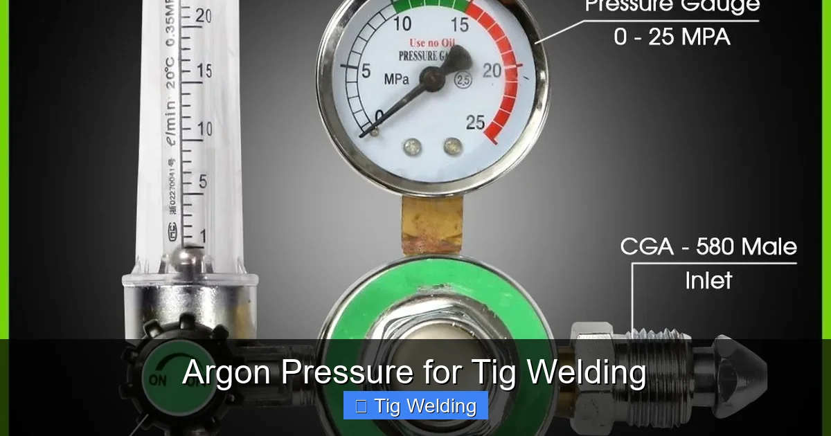
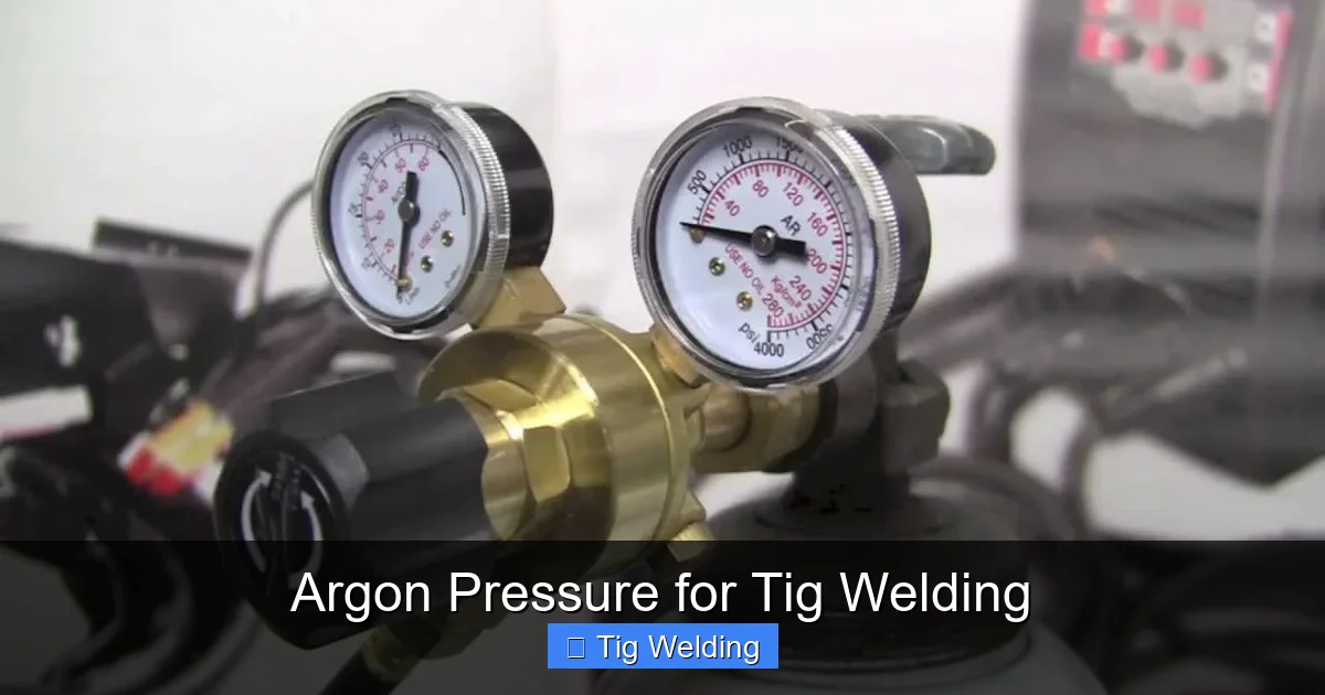
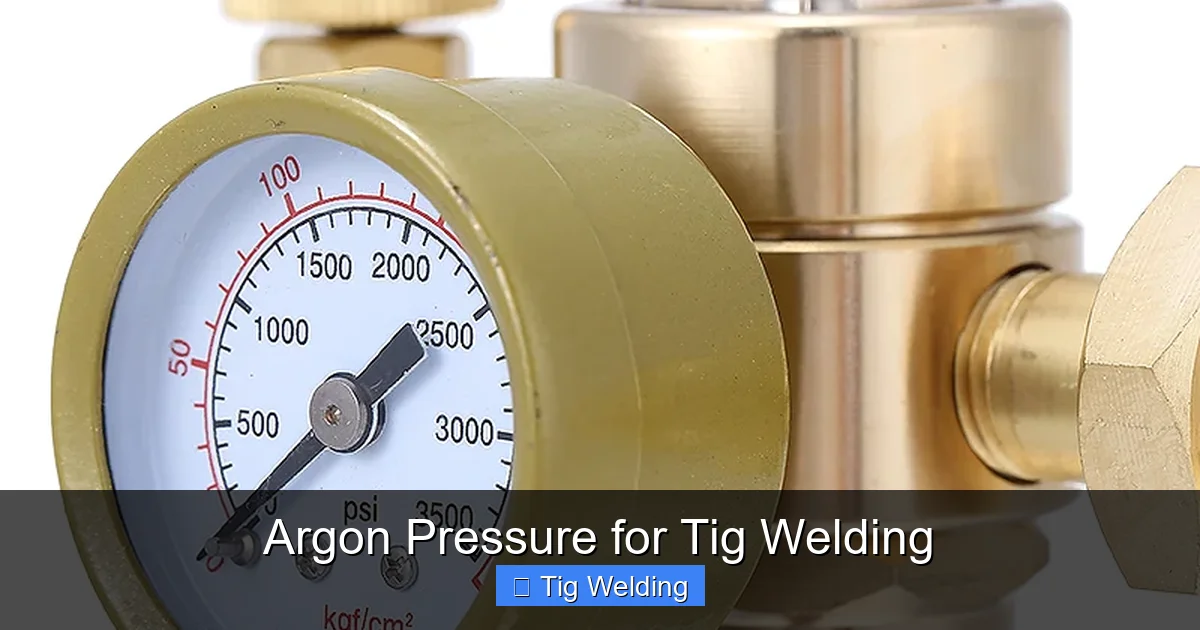
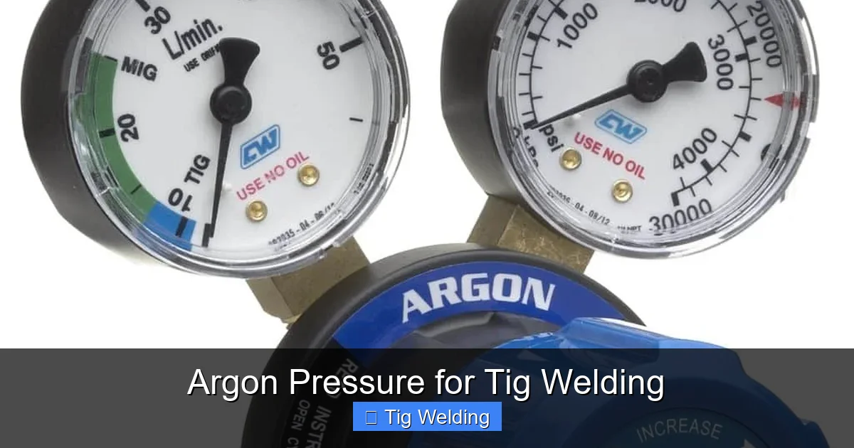
It’s important to clarify terminology. When we discuss “argon pressure” in the context of TIG welding, we’re generally referring to the *flow rate* of the gas. Your argon cylinder has a high-pressure regulator attached to it. This regulator has two gauges: one shows the cylinder pressure, and the other shows the *regulated pressure* or flow rate delivered to your torch. Most TIG welding setups use a flowmeter regulator, which directly indicates the flow rate in CFH or LPM.
The regulated pressure is what you will adjust. This is the force with which the argon is pushed through your torch. The goal is to achieve a consistent, steady stream of argon that adequately covers the weld zone without excessive turbulence.
Visual guide about Argon Pressure for Tig Welding
Image source: i.ytimg.com
Factors Influencing Your Argon Flow Rate
Determining the correct argon flow rate isn’t a one-size-fits-all situation. Several factors come into play, and understanding them will help you make informed decisions:
Visual guide about Argon Pressure for Tig Welding
Image source: images.nexusapp.co
1. Material Type
Different metals have varying sensitivities to atmospheric contamination. Some materials, like stainless steel and titanium, are highly reactive and require robust shielding. Others, like mild steel, are more forgiving.
- Mild Steel: Generally requires a lower flow rate. Around 15-20 CFH (7-9 LPM) is a common starting point.
- Stainless Steel: More prone to oxidation, so it needs better shielding. Aim for 20-25 CFH (9-12 LPM).
- Aluminum: While TIG welding aluminum is done with AC, it’s also sensitive to oxidation. A flow rate of 20-25 CFH (9-12 LPM) is often recommended.
- Titanium: Extremely reactive. It demands the highest level of shielding, often requiring 25-35 CFH (12-16 LPM) or even more, especially for critical applications.
2. Joint Type and Thickness
The geometry of your joint and the thickness of the material significantly impact how much shielding gas is needed.
- Butt Welds: These are open joints. The molten puddle is exposed. You’ll typically need a moderate flow rate, perhaps in the 15-25 CFH (7-12 LPM) range, depending on material and thickness.
- Lap Welds: These joints have a bit more surface area and can trap more atmosphere. A slightly higher flow rate, around 20-25 CFH (9-12 LPM), might be beneficial.
- Corner Welds: Similar to lap welds, the geometry can create pockets where air might linger. Start with 20-25 CFH (9-12 LPM).
- Thick Materials: Thicker materials require more heat and thus a larger molten puddle. A larger puddle needs more shielding gas to be fully protected. For thicker sections, consider increasing the flow rate by 2-5 CFH (1-2 LPM) for every 1/8 inch (3mm) of material thickness beyond the initial setup.
- Thin Materials: For very thin materials, you can often use a lower flow rate to avoid excessive heat input and warping. Start at the lower end of the recommended range for the material.
3. Shielding Gas Nozzle Size
The size of the gas lens or standard nozzle on your TIG torch plays a crucial role. A larger nozzle creates a wider cone of gas, which is beneficial for thicker materials or when welding at a greater distance from the workpiece.
- Small Nozzles (e.g., Size 4 or 6): These are best for intricate work on thin materials where you need precise control and can get close to the weld. They typically require lower flow rates, perhaps 10-20 CFH (5-9 LPM).
- Medium Nozzles (e.g., Size 8): A good all-rounder. Suitable for most general welding applications on mild to medium-thickness materials. Flow rates of 15-25 CFH (7-12 LPM) are common.
- Large Nozzles (e.g., Size 10 or 12): These are ideal for welding thicker materials, aluminum, or stainless steel, especially when you need to maintain a bit more distance or when working with a gas lens. They require higher flow rates, typically 20-30+ CFH (9-14+ LPM).
Using a gas lens is highly recommended for most TIG welding. A gas lens creates a smoother, more laminar (less turbulent) flow of argon, extending the shielding cone further and providing better protection, especially at a slight distance from the workpiece. With a gas lens, you can often achieve better coverage with a slightly lower flow rate compared to a standard nozzle.
4. Amperage and Travel Speed
As you increase your welding amperage, you generate more heat and a larger molten puddle. This larger puddle requires more argon to protect it. Similarly, if you’re welding faster, the shielding gas has less time to react with the atmosphere before the puddle solidifies.
- Higher Amperage: If you’re welding at high amperages (e.g., 150+ amps for thicker steel), you’ll likely need to increase your argon flow rate to ensure the entire puddle is shielded.
- Faster Travel Speed: If you’re moving quickly across the joint, you might need a slightly higher flow rate to compensate for the reduced time the gas has to work.
5. Environmental Factors
This is often overlooked but can be a major contributor to weld defects.
- Drafts and Air Currents: Welding in a drafty shop, outdoors, or near an open door requires a significantly higher argon flow rate. Air currents can easily blow away your shielding gas, leaving the molten puddle exposed. In very windy conditions, TIG welding might be impractical without specialized shielding setups.
- Enclosed Spaces: While it might seem counterintuitive, welding in a very confined space might require slightly less flow to avoid building up excessive gas pressure around the weld zone, though this is less common.
Step-by-Step: Setting Your Argon Flow Rate
Here’s a practical approach to setting your argon flow rate:
Visual guide about Argon Pressure for Tig Welding
Image source: electroweld.com.au
Step 1: Consult Reference Charts
Start with recommended settings. Many TIG welding equipment manufacturers and welding handbooks provide charts that suggest argon flow rates based on material type, thickness, and joint type. These are excellent starting points. For example, a common starting point for 1/8″ (3mm) mild steel with a size 8 nozzle might be 20 CFH (9 LPM).
Step 2: Prepare Your Torch and Regulator
* Ensure your TIG torch is properly connected to your TIG welder and the argon gas line.
* Make sure your flowmeter regulator is securely attached to the argon cylinder valve.
Step 3: Set the Initial Flow Rate
* With the regulator set to your initial desired flow rate (e.g., 20 CFH), open the cylinder valve slowly.
* You should see the ball in the flowmeter tube rise to the set level.
Step 4: Perform a Pre-Weld Gas Purge
Before striking an arc, press the gas button on your TIG torch to allow argon to flow. Do this for about 10-15 seconds. This purges any air from the torch and hose, ensuring that the first moment of welding is shielded.
Step 5: Strike the Arc and Observe
Strike your arc on a test piece or scrap material. While welding, pay close attention to the appearance of your weld puddle and the bead.
Observe the Weld Puddle
* Is it shiny and clean?
* Does it appear free of discoloration (like yellow or blue hues around the edges), which can indicate oxidation?
* If you see signs of contamination or discoloration, you might need more argon.
Observe the Weld Bead
* Is the bead smooth and consistent?
* Are there any signs of porosity (small holes in the weld)? Porosity is a strong indicator of insufficient shielding.
Step 6: Adjust Flow Rate as Needed
Based on your observations, you may need to adjust the flow rate.
Too Little Argon (Signs: Discoloration, Porosity, Dull Weld)
If you notice any of these issues, increase your argon flow rate by 2-3 CFH (1-1.5 LPM) at a time. Perform another test weld and observe again.
Too Much Argon (Signs: Excessive Turbulence, “Whipping” of Gas, Potential for Contamination, Warping)
If you hear a loud “whooshing” sound from the torch, see the argon visibly blowing the molten puddle around, or notice the weld bead looking “dirty” or uneven, you might have too much flow. Decrease your argon flow rate by 1-2 CFH (0.5-1 LPM) at a time. Sometimes, a very high flow rate can actually create turbulence that pulls in atmospheric contaminants, which is the opposite of what you want.
Step 7: Consider the Post-Weld Gas Flow
Just as important as the pre-weld purge is the post-weld gas flow. After you release the trigger, the arc stops, but the molten puddle is still hot and susceptible to contamination. You need to keep the argon flowing for a few seconds *after* the arc is extinguished.
- Recommended Post-Flow Time: A good rule of thumb is 1-2 seconds of post-flow for every 10 amps of welding current, or a minimum of 5-10 seconds.
- Signs of Insufficient Post-Flow: If the end of your weld bead looks discolored or oxidized, you likely need more post-flow time.
- Adjusting Post-Flow: Your TIG welder should have a setting for post-flow time. Refer to your machine’s manual to adjust this.
Practical Tips for Optimizing Argon Pressure
* Use a Gas Lens: If you’re serious about TIG welding, invest in a gas lens kit. They dramatically improve shielding gas coverage and efficiency, allowing you to achieve better welds with less argon in many cases.
* Maintain Proper Stick-Out: Keep your tungsten electrode at the correct stick-out distance (the length of the tungsten protruding from the collet). Too much stick-out can cause poor gas coverage and tungsten contamination. A good starting point for mild steel is about 1/4 to 3/8 inch (6-10mm).
* Angle Your Torch Correctly: Hold your TIG torch at a slight angle (around 5-15 degrees) in the direction of travel. This helps the argon flow over the leading edge of the puddle. Avoid holding the torch perfectly vertical.
* Be Mindful of Weld Pool Size: Always ensure your argon flow is sufficient for the size of your molten puddle. A larger puddle needs more shielding.
* Practice Makes Perfect: The best way to learn is by doing. Use scrap pieces of the same material you’ll be welding. Experiment with different flow rates and observe the results. Document your settings for different applications.
* Check for Leaks: Periodically check your argon hose and connections for leaks. Even a small leak can waste gas and compromise your shielding. You can do this by applying soapy water to connections; if bubbles form, there’s a leak.
Troubleshooting Common Argon Pressure Issues
| Problem | Possible Cause | Solution |
| :———————– | :————————————————– | :——————————————————————————————————— |
| **Porosity (small holes)** | Insufficient argon flow or post-flow. | Increase flow rate. Ensure adequate pre- and post-weld gas purge. Check for drafts. Use a gas lens. |
| **Discoloration (yellow/blue)** | Insufficient argon flow or post-flow. | Increase flow rate. Ensure adequate pre- and post-weld gas purge. Check for drafts. Use a gas lens. |
| **Dull or Matte Weld Bead** | Insufficient argon flow or contamination. | Increase flow rate. Ensure proper shielding. Clean base metal thoroughly. |
| **Warping on Thin Metal** | Excessive argon flow creating too much turbulence. | Decrease argon flow. Consider a smaller nozzle or gas lens. Reduce pre-flow. |
| **Tungsten Contamination** | Poor gas coverage, touching tungsten to puddle. | Ensure adequate gas flow. Maintain correct electrode stick-out. Adjust torch angle. Avoid dipping tungsten. |
| **”Whooshing” Noise** | Excessive argon flow. | Decrease argon flow rate. |
Conclusion
Mastering **argon pressure for TIG welding** is fundamental to achieving professional-quality welds. It’s not a complex science, but it requires a solid understanding of the principles of shielding gas and a willingness to experiment and observe. By considering the material, joint type, nozzle size, amperage, travel speed, and environmental conditions, you can set yourself up for success. Always start with recommended settings, perform your pre- and post-weld purges diligently, and fine-tune your flow rate based on the visual cues your weld provides. With practice and attention to detail, you’ll soon find that dialing in the perfect argon flow becomes second nature, leading to stronger, cleaner, and more beautiful TIG welds. Happy welding!
