

This guide teaches you how to use a MIG welding voltage wire speed chart to achieve clean, strong welds on different metals. You’ll learn the right settings for steel, aluminum, and stainless steel, plus tips to avoid common mistakes.
Key Takeaways
- Voltage and wire speed must match: Incorrect settings cause spatter, weak welds, or burn-through.
- Material thickness matters: Thicker metals need higher voltage and slower wire feed.
- Use the right gas: C25 (75% argon/25% CO2) works best for mild steel; pure argon is ideal for aluminum.
- Start with manufacturer charts: Most welders include recommended settings—use them as a baseline.
- Fine-tune with test welds: Always do a practice run on scrap metal before welding your final piece.
- Keep your gun clean: A dirty contact tip or liner affects wire feeding and weld quality.
- Adjust for position: Vertical and overhead welding may require lower voltage to control the puddle.
Understanding the MIG Welding Voltage Wire Speed Chart
If you’re new to MIG welding, one of the first things you’ll notice is how many settings there are to adjust. Among the most important are voltage and wire speed. These two settings control how much heat goes into the metal and how fast the wire is fed into the weld pool. Getting them right is key to making strong, clean welds.
A MIG welding voltage wire speed chart is a handy reference that tells you the recommended voltage (measured in volts) and wire feed speed (measured in inches per minute, or IPM) for different materials and thicknesses. These charts are usually provided by welding machine manufacturers or wire suppliers. They’re not magic, but they’re a great starting point.
In this guide, you’ll learn how to read and use these charts, adjust settings for your specific project, and troubleshoot common issues. Whether you’re welding thin sheet metal or thick steel plates, this guide will help you dial in the perfect settings every time.
Why Voltage and Wire Speed Matter
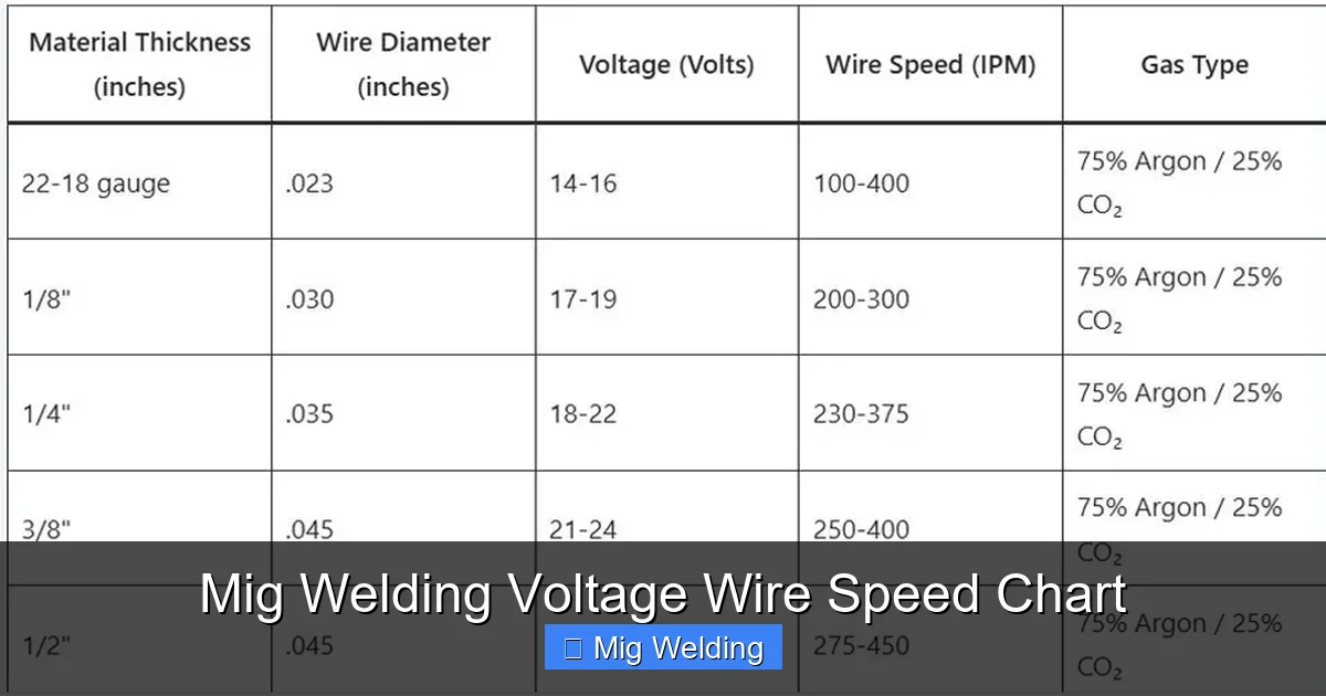
Visual guide about Mig Welding Voltage Wire Speed Chart
Image source: weldingproperty.com
Voltage controls the arc length and heat input. Higher voltage creates a longer arc and more heat, which is good for thicker materials. Too much voltage causes spatter, burn-through, and a rough weld bead. Too little voltage leads to a short arc, poor penetration, and a narrow, ropey bead.
Wire speed determines how much filler metal is deposited. Faster wire speed increases deposition rate but also increases current. If wire speed is too high for the voltage, the wire can stub into the weld pool. If it’s too low, the arc struggles to stay stable.
The goal is to find the sweet spot where voltage and wire speed work together to create a smooth, consistent arc and a strong weld. This balance changes based on material type, thickness, and welding position.
How to Read a MIG Welding Voltage Wire Speed Chart
Visual guide about Mig Welding Voltage Wire Speed Chart
Image source: settingslab.com
Most charts are organized by material type and thickness. Here’s how to use one:
Step 1: Identify Your Material
Common materials include:
- Mild steel (most common)
- Stainless steel
- Aluminum
Each material requires different settings due to differences in melting point and conductivity.
Step 2: Determine Material Thickness
Measure the thickest part of the joint. Charts usually list thicknesses in inches or millimeters. For example:
- 18-gauge steel = 0.047 inches
- 1/8 inch = 0.125 inches
- 1/4 inch = 0.25 inches
Step 3: Find the Recommended Settings
Look for your material and thickness on the chart. You’ll see a range for voltage (e.g., 18–20 volts) and wire speed (e.g., 200–250 IPM). These are starting points.
Step 4: Adjust for Wire Diameter
Common wire sizes:
- 0.023″ – for thin materials (under 1/8″)
- 0.030″ – general purpose
- 0.035″ – for thicker steel
- 0.045″ – for heavy fabrication
Thicker wires need higher voltage and slower wire speed.
Sample MIG Welding Settings Chart
Here’s a simplified chart for mild steel using 0.030″ wire and C25 gas:
| Thickness (inches) | Voltage (volts) | Wire Speed (IPM) |
|---|---|---|
| 18-gauge (0.047″) | 16–18 | 180–220 |
| 16-gauge (0.060″) | 17–19 | 200–240 |
| 14-gauge (0.078″) | 18–20 | 220–260 |
| 1/8″ (0.125″) | 19–21 | 240–280 |
| 3/16″ (0.187″) | 20–22 | 260–300 |
| 1/4″ (0.25″) | 21–23 | 280–320 |
Note: These are general guidelines. Always test on scrap metal first.
Setting Up Your Welder
Once you have your settings, it’s time to dial them in.
Step 1: Set the Voltage
Turn the voltage knob to the recommended setting. Most machines have a digital display or labeled dial.
Step 2: Set the Wire Speed
Adjust the wire feed speed using the IPM setting. Some machines use a dial; others have a digital input.
Step 3: Check Gas Flow
Set your regulator to 20–25 CFH (cubic feet per hour). Too little gas causes porosity; too much wastes gas and can disturb the arc.
Step 4: Test on Scrap Metal
Weld a short bead on a piece of scrap with the same thickness. Look for:
- A smooth, even bead
- Minimal spatter
- Good penetration (check by bending or grinding)
Fine-Tuning Your Settings
Even with a chart, you may need small adjustments.
If the Weld is Too Cold (Low Heat)
- Symptoms: Ropey bead, lack of fusion, wire stubbing
- Fix: Increase voltage slightly or increase wire speed
If the Weld is Too Hot (High Heat)
- Symptoms: Burn-through, excessive spatter, wide bead
- Fix: Lower voltage or reduce wire speed
If There’s Too Much Spatter
- Cause: Voltage too high or wire speed too low
- Fix: Reduce voltage or increase wire speed
If the Arc is Unstable
- Cause: Dirty contact tip, wrong polarity, or poor ground
- Fix: Clean or replace the tip, check ground clamp, ensure correct polarity (DC+ for most MIG welding)
Special Considerations for Different Materials
Mild Steel
Most forgiving material. Use C25 gas and standard ER70S-6 wire. Follow the chart closely.
Stainless Steel
Use ER308L or ER309L wire and tri-mix gas (argon/CO2/O2) or argon/CO2. Voltage is similar to mild steel, but wire speed may be slightly lower. Pre-clean with a stainless wire brush.
Aluminum
Requires pure argon gas and aluminum-specific wire (e.g., ER4043 or ER5356). Use a spool gun or push-pull gun to prevent birdnesting. Voltage is lower than steel—typically 16–20 volts for 1/8″ material. Wire speed is higher due to softer wire.
Troubleshooting Common MIG Welding Problems
Porosity (Air Pockets in Weld)
- Cause: Contaminated base metal, low gas flow, or wind
- Fix: Clean metal with grinder or solvent, check gas flow, weld in sheltered area
Undercut (Groove at Weld Edge)
- Cause: Travel speed too fast or voltage too high
- Fix: Slow down travel speed, reduce voltage slightly
Lack of Fusion
- Cause: Low heat input or incorrect angle
- Fix: Increase voltage, use a push technique, ensure proper joint fit-up
Wire Feeding Problems
- Cause: Worn drive rolls, dirty liner, or incorrect tension
- Fix: Clean or replace liner, adjust drive roll tension, use correct roll for wire type
Tips for Consistent Results
- Always clean your metal before welding—oil, rust, and paint ruin welds.
- Use a consistent travel speed—too fast = weak weld; too slow = burn-through.
- Keep your gun at a 10–15 degree angle and maintain a 1/2″ to 3/4″ stick-out.
- Store welding wire in a dry place to prevent moisture absorption.
- Regularly inspect and replace worn parts like contact tips and nozzles.
Conclusion
Using a MIG welding voltage wire speed chart doesn’t have to be confusing. Start with the recommended settings, test on scrap metal, and make small adjustments as needed. Remember, every welder, material, and environment is a little different—so don’t be afraid to experiment.
With practice, you’ll develop a feel for the right settings and be able to weld confidently on any project. Whether you’re fixing a trailer, building a frame, or crafting art, mastering voltage and wire speed is the foundation of great MIG welding.
Keep this guide handy, refer to your machine’s chart, and always prioritize safety. Happy welding!