

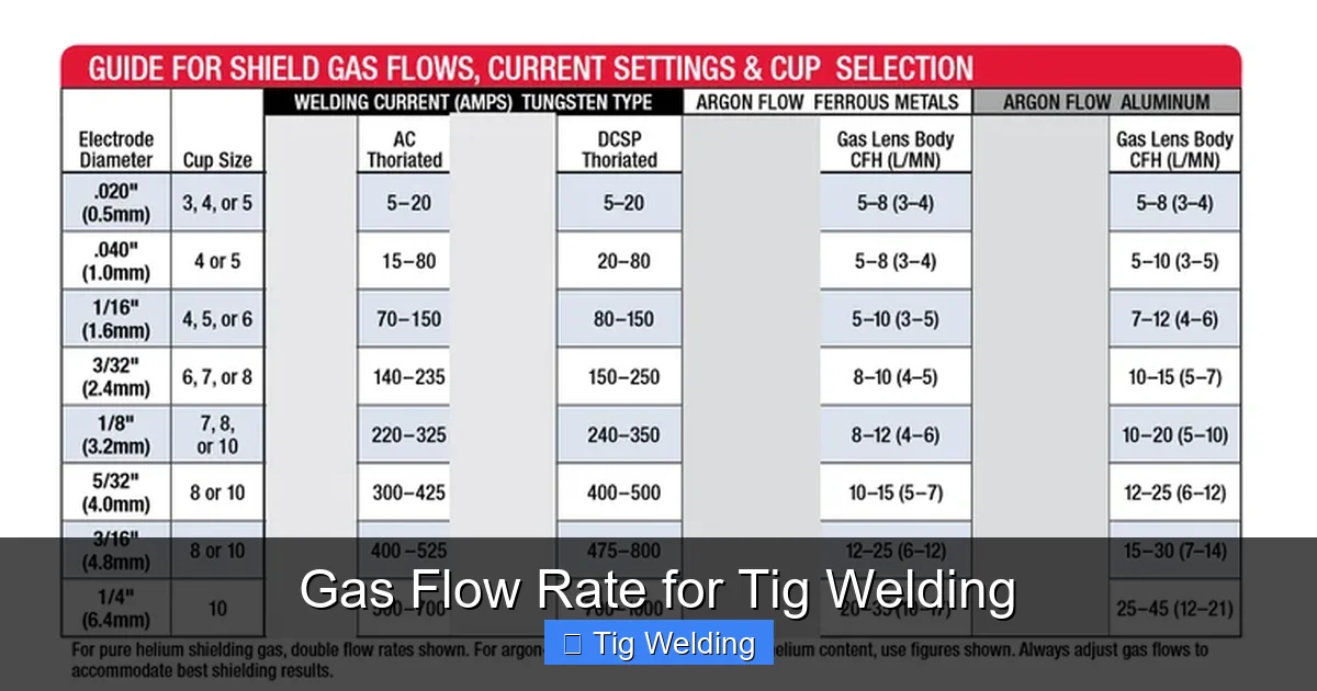
Proper TIG welding gas flow rate is crucial for weld quality and preventing defects. This guide explores how gas protects your weld puddle, offering step-by-step instructions to find the ideal settings for various metals and situations. Learn to adjust your flow rate based on amperage, joint type, and environmental conditions for consistently beautiful and strong TIG welds.
Gas Flow Rate for Tig Welding: Your Ultimate Guide to Perfect Protection
TIG welding, also known as Gas Tungsten Arc Welding (GTAW), is renowned for its precision, control, and ability to produce exceptionally clean and strong welds. However, achieving those hallmark welds isn’t just about mastering torch angle and filler metal manipulation. A critical, often overlooked, factor that significantly impacts weld quality is the gas flow rate. Too little, and your weld is vulnerable to contamination. Too much, and you can cause turbulence, leading to porosity and other defects. This guide will demystify TIG welding gas flow rate, equipping you with the knowledge to set it correctly for a wide range of applications.
Key Takeaways
- Understanding Shielding Gas: Argon, helium, and their mixtures protect the molten weld puddle from atmospheric contamination, which is vital for strong, clean welds.
- Flow Rate Basics: The flow rate, measured in cubic feet per hour (CFH) or liters per minute (LPM), dictates how effectively the shielding gas displaces oxygen and nitrogen.
- Amperage is Key: Higher amperage generally requires a higher gas flow rate to ensure adequate shielding coverage over a larger, hotter puddle.
- Metal Matters: Different metals have varying sensitivities to atmospheric contamination, influencing the optimal gas flow rate needed for a successful weld.
- Joint Design and Fit-Up: Open joints or poor fit-up can lead to gas turbulence or insufficient coverage, necessitating adjustments to the flow rate.
- Environmental Factors: Wind or drafts can disrupt the shielding gas, requiring higher flow rates or protective measures to maintain coverage.
- Finding Your Sweet Spot: There’s no single magic number; finding the correct gas flow rate involves a combination of guidelines, observation, and practice.
Why is Gas Flow Rate So Important in TIG Welding?
The primary role of the shielding gas in TIG welding is to create a protective atmosphere around the tungsten electrode, the molten weld puddle, and the newly formed weld bead. This barrier prevents atmospheric gases, primarily oxygen and nitrogen, from reacting with the hot, molten metal. If these gases get into the weld, they can cause:
- Porosity: Tiny gas bubbles trapped within the solidified weld, weakening it.
- Oxidation: A discolored, brittle, and often weaker weld.
- Inclusions: Contaminants becoming part of the weld metal.
The gas flow rate directly controls the volume and velocity of this protective shield. It needs to be enough to displace all surrounding air effectively but not so much that it becomes chaotic and pulls in atmospheric contaminants.
Understanding Your Shielding Gas
Before diving into flow rates, let’s briefly touch on the common shielding gases used in TIG welding:
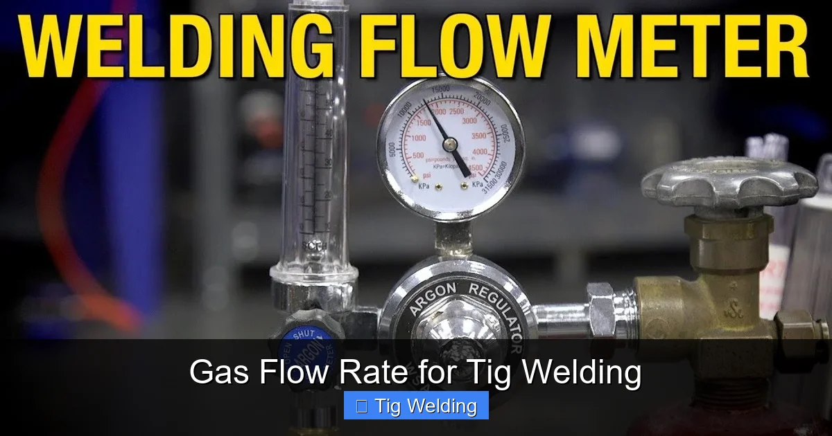
Visual guide about Gas Flow Rate for Tig Welding
Image source: i.ytimg.com
- Argon (Ar): The most common TIG shielding gas. It’s denser than air and provides excellent arc stability and penetration, especially on thinner materials and metals like aluminum and stainless steel.
- Helium (He): Lighter and more expensive than argon. It provides a hotter arc with broader penetration, making it suitable for thicker materials or when faster travel speeds are desired. It can also help reduce tungsten contamination.
- Argon-Helium Mixtures: These blend the benefits of both gases. For instance, an 75% Argon / 25% Helium mix offers a hotter arc than pure argon but is more controllable than pure helium.
- Argon-CO2 Mixtures (less common for TIG): While prevalent in MIG welding, CO2 is generally avoided in TIG due to its tendency to cause oxidation and affect arc quality.
The type of gas influences the ideal flow rate, with denser gases like argon potentially requiring a slightly different approach than lighter gases or mixtures.
Factors Influencing Gas Flow Rate
Setting the right gas flow rate isn’t a one-size-fits-all scenario. Several factors come into play:

Visual guide about Gas Flow Rate for Tig Welding
Image source: i.ytimg.com
- Amperage: This is arguably the most significant factor. Higher amperage creates a larger, hotter weld puddle that requires a more robust shielding gas envelope.
- Type of Metal: Different metals have different sensitivities to atmospheric contamination. For example, aluminum oxidizes very quickly and requires excellent shielding.
- Joint Type and Fit-Up: Open butt joints, corner joints, and situations with gaps or poor fit-up can lead to gas escaping or being disturbed.
- Torch and Nozzle Size: A larger nozzle on your TIG torch requires a higher flow rate to fill its effective coverage area.
- Welding Position: Out-of-position welding (vertical, overhead) can sometimes make gas coverage more challenging.
- Environmental Conditions: Drafts, wind, or even significant air movement in the workshop can disrupt the shielding gas.
- Tungsten Electrode Stickout: The amount the tungsten electrode protrudes from the gas nozzle can affect gas coverage efficiency.
How to Determine the Correct Gas Flow Rate
The process involves a combination of understanding general guidelines and fine-tuning based on observation and testing.
Visual guide about Gas Flow Rate for Tig Welding
Image source: multec.com.au
Step 1: Consult Manufacturer Recommendations and General Guidelines
Your TIG welding machine manufacturer, or the manufacturer of your shielding gas regulator, will often provide charts or recommendations for gas flow rates based on amperage. These are excellent starting points.
A common rule of thumb for pure Argon is:
- For thinner materials (under 1/8 inch) and lower amperages (15-50 amps): 10-15 CFH (20-30 LPM)
- For medium materials (1/8 to 1/4 inch) and moderate amperages (50-150 amps): 15-25 CFH (30-45 LPM)
- For thicker materials (over 1/4 inch) and higher amperages (150+ amps): 20-30 CFH (40-60 LPM)
Note: These are general guidelines. Helium and helium mixtures often require slightly higher flow rates due to their lighter nature.
Step 2: Set Your Regulator
Your TIG welding setup will have a gas regulator attached to the shielding gas cylinder. This regulator has a flowmeter that allows you to adjust the flow rate.
H3: Adjusting the Flowmeter
Most flowmeters use a ball inside a calibrated tube. To adjust the flow rate:
- Ensure the shielding gas valve on your regulator is turned off.
- Slowly open the valve on the gas cylinder.
- Observe the ball in the flowmeter tube.
- Slowly turn the adjustment knob on the regulator. For most regulators, turning it counter-clockwise will increase the flow rate, and clockwise will decrease it.
- Adjust the knob until the ball sits at the desired setting on the scale (e.g., 20 CFH or 40 LPM).
- Once set, close the gas cylinder valve and then open the regulator valve. This will reset the ball to zero and allow you to measure without gas flowing.
- When ready to weld, open the cylinder valve, then the regulator valve. You should see the ball rise to your set flow rate.
Important: Always use a regulator specifically designed for the gas you are using. Different gases can have different pressure requirements and compatibility issues.
Step 3: Perform a Test Weld and Observe
This is where practice and keen observation come in. After setting your initial flow rate, perform a test weld on scrap material similar to your project. Pay attention to the following:
H3: Evaluating Shielding Gas Coverage
While welding, and immediately after you finish the bead, look for signs of good or bad gas coverage:
- Color of the Weld: A clean, bright weld bead, often with a slight iridescent sheen (like straw or light blue on stainless steel), indicates good shielding. A dark, sooty, or heavily discolored bead suggests contamination.
- Porosity: Look for small pinholes or bubbles in the solidified weld. This is a clear sign of insufficient shielding.
- Arc Stability: A stable, consistent arc is easier to maintain with proper gas flow. Excessive gas can sometimes make the arc seem “flappy” or unstable.
- Molten Puddle Appearance: The molten puddle should appear smooth and fluid, without signs of oxidation creeping in from the edges.
H3: Fine-Tuning the Flow Rate
Based on your observations, make small adjustments to the gas flow rate:
- If you see porosity or discoloration: Increase the gas flow rate slightly (e.g., by 1-2 CFH or 2-5 LPM).
- If the arc seems unstable, or you notice a “blowing out” effect on the puddle: Decrease the gas flow rate slightly. Too much gas can create turbulence, sucking in air.
- If the weld appears clean but you’re using a higher flow rate than recommended: You might be able to reduce it slightly to save gas and potentially achieve a more focused arc.
Step 4: Consider Specific Materials and Applications
While the general guidelines are a good starting point, some materials and situations benefit from specific adjustments:
H3: Aluminum Welding
Aluminum oxidizes rapidly. While argon is common, for thicker aluminum (over 1/4 inch), an Argon-Helium mix (e.g., 75% Ar / 25% He) can be beneficial. Helium provides deeper penetration and a hotter arc, which is often needed for aluminum. You might need a slightly higher flow rate for helium mixes compared to pure argon.
H3: Stainless Steel Welding
Stainless steel is also prone to oxidation and discoloration. Pure argon is standard. Ensure consistent coverage, especially on the backside of the weld if accessible. For critical applications, backing gas (purging the back of the joint with pure argon) is highly recommended to prevent sugaring (a rough, oxidized surface on the back).
H3: Thin Sheet Metal
For very thin materials, a lower amperage and a slightly lower, but still adequate, gas flow rate are usually sufficient. Over-gassing can blow the molten puddle around too much.
H3: Thick Materials
As mentioned, higher amperage means a larger puddle, requiring more shielding. Consider increasing the flow rate, and for very thick sections, Argon-Helium mixes can be advantageous.
H3: Out-of-Position Welding
In vertical or overhead positions, gravity can make it harder for the gas to stay in place. You might need to slightly increase the flow rate or adjust your torch angle to direct the gas effectively. Be careful not to create too much turbulence.
Step 5: Account for Environmental Factors
Welding in an open garage or outdoors presents a challenge. Air movement can easily disrupt the delicate shielding gas envelope.
H3: Dealing with Drafts and Wind
If you’re experiencing drafts:
- Increase gas flow rate: A higher flow rate can help push back the ambient air more effectively.
- Use a larger gas nozzle: A larger nozzle provides a wider cone of shielding gas, offering better protection.
- Create a windbreak: Use screens, welding curtains, or even your body to shield the weld area from air currents.
- Consider a gas lens: A gas lens kit for your TIG torch can significantly improve gas coverage, especially at longer tungsten stickouts and in less-than-ideal conditions.
Note: Over-gassing due to wind can lead to the same issues as insufficient shielding – turbulence and contamination.
Troubleshooting Common Gas Flow Issues
Here’s a quick guide to common problems and their likely solutions related to gas flow:
- Problem: Porosity (pinholes in the weld)
Cause: Insufficient shielding gas coverage.
Solution: Increase gas flow rate. Check for leaks in the gas line. Ensure adequate tungsten stickout. Consider a gas lens. - Problem: Discoloration (straw, blue, grey, or black weld bead)
Cause: Oxidation due to insufficient shielding or atmospheric contamination.
Solution: Increase gas flow rate. Check for leaks. Ensure the weld area is clean before welding. - Problem: Arc Instability or “Fluttering”
Cause: Excessive gas flow rate creating turbulence, or a leak allowing air in.
Solution: Decrease gas flow rate. Check for leaks. Ensure regulator is functioning correctly. - Problem: Tungsten Contamination (tungsten particles in the weld)
Cause: Arc wander, touching the tungsten to the puddle, or poor gas coverage.
Solution: Ensure proper gas flow and coverage. Maintain a consistent arc length and angle. - Problem: “Sugaring” on the back of the weld (especially stainless steel)
Cause: Insufficient or no shielding on the backside of the weld.
Solution: Use backing gas (purging with argon) if possible. Ensure adequate gas coverage from the front if purging isn’t an option.
Tips for Optimizing Gas Flow Rate
- Always use a surge tank: If your TIG machine has a gas solenoid, it controls gas flow. However, a surge tank can help ensure a consistent flow at the start of the weld.
- Experiment with tungsten stickout: A shorter tungsten stickout generally provides better gas coverage. However, gas lenses allow for longer stickouts while maintaining excellent coverage.
- Cleanliness is paramount: No amount of shielding gas can compensate for a dirty base metal or filler rod. Always clean your materials thoroughly.
- Listen to your arc: Experienced welders often learn to “hear” if their gas flow is correct. A good arc has a consistent, steady sound.
- Document your settings: For critical jobs, record the gas flow rate along with amperage, tungsten type, and gas lens size that worked best.
Conclusion
Mastering TIG welding gas flow rate is an essential skill for any welder aiming for high-quality results. It’s a balancing act – providing enough shielding to protect your molten metal from atmospheric contamination without causing turbulence that introduces its own set of problems. By understanding the factors involved, starting with recommended guidelines, and carefully observing your test welds, you can fine-tune your gas flow to achieve clean, strong, and aesthetically pleasing TIG welds every time. Remember, practice and attention to detail are your best tools in achieving welding perfection.
