


Understanding and correctly setting TIG welding gas pressure is crucial for achieving strong, clean, and aesthetically pleasing welds. This guide breaks down why gas is vital, how to determine the right flow rate for Argon, and practical steps for setting and monitoring your pressure. By mastering this fundamental aspect of TIG welding, you’ll significantly improve your weld quality and efficiency.
Tig Welding Gas Pressure
Welcome to our comprehensive guide on TIG welding gas pressure! If you’re looking to take your TIG welding skills to the next level, understanding how to properly set and manage your shielding gas is absolutely essential. Many welders, especially beginners, might overlook the finer points of gas pressure, but it’s one of the most critical factors in achieving beautiful, strong, and defect-free welds.
In this guide, we’ll dive deep into everything you need to know about TIG welding gas. You’ll learn why shielding gas is so important, how to determine the correct flow rate for your specific application, and the practical steps involved in setting and monitoring your gas pressure. By the end of this article, you’ll have the confidence to dial in your gas settings for every TIG job, leading to cleaner welds and a more enjoyable welding experience. Let’s get started!
Key Takeaways
- Shielding Gas Importance: Inert shielding gas, typically Argon for TIG, protects the molten weld pool from atmospheric contaminants like oxygen and nitrogen, which cause porosity and weak welds.
- Flow Rate vs. Pressure: It’s essential to understand that the dial on your regulator shows pressure (PSI), but what matters most for welding is the flow rate (CFH or L/min).
- Factors Influencing Flow Rate: Proper gas flow depends on amperage, joint type, material thickness, welding position, and environmental conditions (drafts).
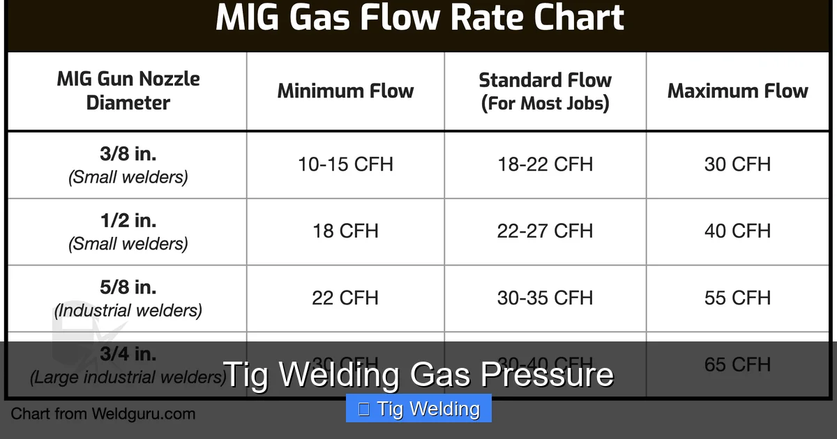
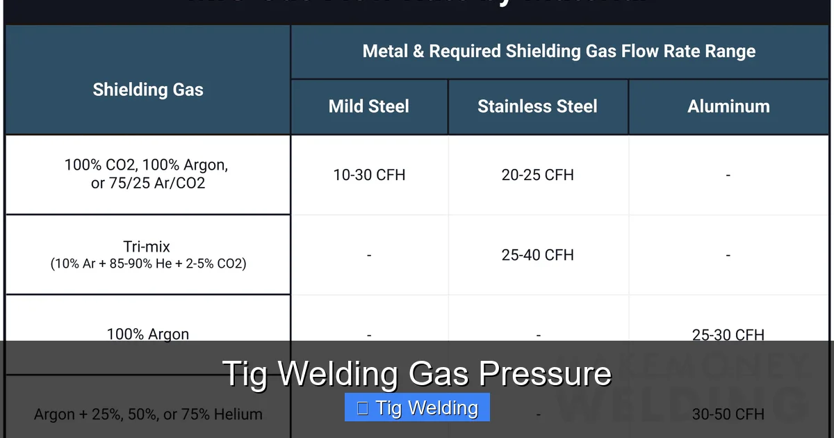
- The “Sweet Spot”: For most TIG welding with Argon, a flow rate between 15-25 cubic feet per hour (CFH) or 7-12 liters per minute (LPM) is a good starting point.
- Estimating Gas Needs: A common rule of thumb is to use approximately 1 CFH of Argon for every 10 amps of welding current.
- Troubleshooting Common Issues: Incorrect gas pressure or flow can lead to weld contamination, arc instability, and a burnt tungsten electrode.
Why is Shielding Gas Crucial in TIG Welding?
Before we get into the nitty-gritty of pressure, let’s quickly cover why shielding gas is so vital. TIG (Tungsten Inert Gas) welding, also known as GTAW (Gas Tungsten Arc Welding), uses an electric arc to create heat and melt the base metal and filler rod (if used). This process happens in an open environment exposed to the air.
Air is full of contaminants, primarily oxygen and nitrogen. When these contaminants come into contact with the super-hot molten weld pool, they react quickly. This reaction can cause:
- Porosity: Tiny bubbles of gas trapped within the solidified weld metal. These bubbles weaken the weld significantly and create a rough, unprofessional appearance.
- Oxidation: A brittle, discolored layer on the surface of the weld and surrounding metal, making it difficult to achieve good fusion and potentially leading to cracking.
- Tungsten Contamination: If the shielding gas fails, the tungsten electrode can get too close to the arc and contaminate the weld pool. This leads to a dirty arc and a very poor-quality weld.
The shielding gas, typically Argon for most TIG applications, is designed to displace the surrounding air and create a protective envelope around the arc and the molten weld pool. This barrier prevents atmospheric contaminants from reaching the hot metal, ensuring a clean, strong, and precise weld.
Understanding Gas Pressure vs. Flow Rate
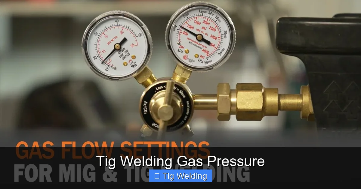
This is a common point of confusion for many new TIG welders. The dial on your gas regulator usually indicates **pressure**, measured in Pounds per Square Inch (PSI). However, what actually matters for effective shielding is the **flow rate** of the gas, measured in Cubic Feet per Hour (CFH) or Liters per Minute (LPM).
Think of it like this: pressure is the force pushing the gas, while flow rate is how much gas is actually moving through the torch and out the nozzle. A high pressure with a very restrictive nozzle would result in a low flow rate. Conversely, a lower pressure with a wide-open valve would result in a higher flow rate.
Your regulator’s job is to take the high pressure from the cylinder and reduce it to a usable, consistent pressure that then feeds into a flow meter (often a ball in a tube or a digital display) which shows the flow rate. It’s this flow rate that we need to set correctly.
Factors Affecting Your Ideal Gas Flow Rate
There’s no single “magic number” for TIG welding gas pressure. The ideal flow rate depends on several factors:
Amperage
Generally, higher amperage welding requires more shielding gas. A hotter arc creates a larger molten pool, which needs a broader and more robust shield to prevent contamination.
Material Thickness
Thicker materials often require higher amperages and thus, more shielding gas. Very thin materials might need less flow to avoid blowing the gas away and causing turbulence.
Joint Type and Preparation
Open butt joints might require a slightly higher flow than corner or lap joints. Proper joint preparation, ensuring clean surfaces, also reduces the risk of contamination and can sometimes allow for slightly lower gas flow.
Welding Position
Welding out-of-position (vertical or overhead) can be trickier. Gravity can affect how the shielding gas settles, potentially requiring slight adjustments to ensure adequate coverage. You might need to increase the flow slightly to counteract the gas being displaced.
Torch Nozzle Size
Larger diameter nozzles provide a wider coverage area for the shielding gas. If you use a larger nozzle, you might need a slightly higher flow rate to fill that larger area effectively.
Drafts and Air Movement
This is a crucial environmental factor. If you’re welding in an area with drafts, fans, or open doors, you’ll need to increase your shielding gas flow rate significantly to overcome the air movement and ensure the gas reaches the weld pool. This is a very common cause of weld contamination.
Setting Your TIG Welding Gas Pressure: A Step-by-Step Guide
Now that we understand the why and what, let’s get to the how. Setting up your gas supply correctly is straightforward once you know the process.
Step 1: Connect Your Gas Cylinder and Regulator
This might seem obvious, but ensuring a secure connection is paramount.
Check the Cylinder Valve
Before attaching the regulator, briefly open the cylinder valve for a second or two. This is called “cracking” the valve. It will blow out any dust or debris that might have accumulated in the valve outlet. Be careful and point the valve away from yourself and others.
Attach the Regulator
Hand-tighten the regulator onto the cylinder valve. Use a wrench to give it a final snug turn, but avoid over-tightening, as this can damage the valve or regulator threads.
Open the Cylinder Valve Slowly
Once the regulator is secure, open the main cylinder valve slowly and fully. You should see the high-pressure gauge on the regulator start to register the cylinder pressure.
Step 2: Set the Regulator Outlet Pressure (if applicable)
Some regulators have an adjustment knob that sets a specific outlet pressure. However, most common TIG welding setups use a regulator with a built-in flow meter, where you directly adjust the flow rate. If your regulator has a high-pressure gauge and a separate valve to control flow, follow its specific instructions. For typical flow meter regulators, you’ll skip this specific step and go directly to flow rate adjustment.
Step 3: Set the Gas Flow Rate
This is the critical step. Most TIG welding flow meters use a ball inside a calibrated tube.
Connect the Gas Line to Your Torch
Ensure the gas line from the regulator is securely connected to the appropriate gas inlet on your TIG torch or welding machine.
Adjust the Flow Control Knob
Locate the adjustment knob on the regulator or flow meter. Slowly turn this knob to raise the flow rate. As you turn it, the ball in the flow tube should rise. Adjust it until the bottom of the ball aligns with the desired flow rate marking on the tube.
Step 4: Test the Gas Flow
Before you start welding, you need to confirm the gas is flowing correctly and check for leaks.
Initiate Gas Flow (Pre-flow)
Most TIG welding machines have a “pre-flow” setting. This allows shielding gas to flow from the torch for a few seconds *before* the arc starts. This is essential for purging air from the torch and creating that protective envelope from the moment the arc ignites.
Listen and Feel for Gas
With the pre-flow activated, listen for the hiss of gas coming from the torch nozzle. You can also feel a gentle flow of gas if you hold your hand a few inches away.
Check for Leaks
While the gas is flowing, check all connections (regulator to cylinder, regulator to hose, hose to torch) for any signs of leaks. You can do this by listening for hissing sounds or by using a leak detection solution (soapy water works well). If you find a leak, shut off the gas immediately and tighten the connection or replace the faulty part.
Step 5: Monitor and Adjust During Welding
Once you start welding, keep an eye (and ear) on your gas flow.
Observe the Arc
An unstable or “dirty” arc can be a sign of inadequate shielding gas. The arc might flicker erratically, or you might see the tungsten electrode begin to contaminate with a gray or black coating.
Look at the Weld Pool
During welding, the molten weld pool should appear bright and shiny. If it looks dull, discolored, or you see tiny bubbles forming on its surface, your shielding gas might be insufficient or disrupted.
Listen for Gas Hiss
A consistent, gentle hiss of gas from the torch is a good indicator of stable flow. A sudden change in sound could signal a problem.
Adjust as Needed
If you notice any of the issues above, stop welding. Check your gas flow rate and consider increasing it slightly. If you’re welding outdoors or in a drafty area, increasing the flow rate is often the solution.
Recommended Gas Flow Rates for Argon
As a general starting point for TIG welding with Argon, here are some common recommendations:
- General Purpose Welding (15-25 CFH / 7-12 LPM): This range covers most common TIG welding applications on steel and stainless steel with standard nozzle sizes (e.g., #6 to #8 ceramic nozzles).
- Thin Materials (< 1/8 inch): You might start at the lower end of the range, around 15-20 CFH (7-9 LPM), to avoid excessive gas usage and potential turbulence.
- Thicker Materials (> 1/4 inch) or Higher Amperage (> 150 Amps): You might need to increase the flow rate to 20-30 CFH (9-14 LPM) or even slightly higher, especially if using larger nozzles or welding in difficult positions.
- Outdoors or Drafty Conditions: Be prepared to increase the flow rate by 5-10 CFH (2-5 LPM) or more to compensate for air movement.
A common rule of thumb is to use approximately 1 CFH of Argon for every 10 amps of welding current. So, for a 100-amp weld, you might start with around 10 CFH, and for a 200-amp weld, around 20 CFH. This is just a starting point; always adjust based on observation.
Troubleshooting Common TIG Gas Issues
Let’s address some problems you might encounter related to TIG welding gas pressure and flow:
Problem: Porous Welds
Cause: Inadequate shielding gas. This could be due to a flow rate that’s too low, drafts disrupting the gas shield, a leak in the gas line, or insufficient pre-flow/post-flow.
Visual guide about Tig Welding Gas Pressure
Image source: weldguru.com
Visual guide about Tig Welding Gas Pressure
Image source: makemoneywelding.com
Visual guide about Tig Welding Gas Pressure
Image source: i.ytimg.com
Solution:
- Increase your flow rate.
- Ensure you are using the correct nozzle size for your amperage and application.
- Check for drafts and try to shield the welding area.
- Perform a leak test on your gas system.
- Ensure your machine’s pre-flow and post-flow settings are appropriate (see below).
Problem: Burnt or Contaminated Tungsten Electrode
Cause: This often happens when the shielding gas fails to protect the tungsten. It could be insufficient flow, drafts, or the tungsten electrode is sticking out too far from the nozzle.
Solution:
- Increase gas flow rate.
- Ensure the tungsten electrode is only sticking out about 1/4 to 1/2 inch from the end of the ceramic nozzle.
- Check for drafts.
- Ensure you have adequate pre-flow to establish the shield before striking the arc.
Problem: Unstable Arc
Cause: Similar to porosity, an unstable arc is usually a sign of poor shielding. This can also be caused by using the wrong type of shielding gas (e.g., using CO2 or a mix not suitable for TIG).
Solution:
- Verify you are using 100% Argon for TIG welding steel, stainless steel, and aluminum.
- Increase your gas flow rate.
- Check for drafts.
Problem: High Gas Consumption / Running Out of Gas Too Quickly
Cause: The flow rate is set too high for the application, or there are significant leaks in the system.
Solution:
- Reduce your flow rate to the minimum required for good shielding.
- Perform a thorough leak check of your entire gas system.
- Ensure your post-flow setting isn’t excessively long.
Pre-Flow and Post-Flow Settings
Your TIG welding machine likely has settings for pre-flow and post-flow duration. These are crucial for proper gas shielding:
- Pre-flow: This setting determines how long the shielding gas flows *before* the arc is initiated. A typical setting is 0.5 to 1 second. This allows you to establish a protective atmosphere around the tungsten and the intended weld area before the arc strikes, preventing immediate contamination.
- Post-flow: This setting determines how long the shielding gas continues to flow *after* the arc is extinguished. A typical setting is 5 to 10 seconds, but this can vary depending on the material and amperage. Post-flow is vital for protecting the cooling weld pool and the hot tungsten electrode from atmospheric contamination as they cool down. Without adequate post-flow, the weld can oxidize, and the tungsten tip can degrade quickly.
Adjusting these settings based on your amperage and material is an important part of gas management.
Conclusion
Mastering TIG welding gas pressure, or more accurately, gas flow rate, is a fundamental skill that will dramatically improve the quality and appearance of your welds. By understanding the role of shielding gas, the difference between pressure and flow, and the factors that influence your ideal settings, you’re well on your way to becoming a more proficient TIG welder.
Remember to always start with recommended flow rates, observe your arc and weld pool closely, and make adjustments as needed. Pay attention to environmental factors like drafts, and don’t forget the importance of pre-flow and post-flow. With practice and attention to detail, you’ll soon be achieving consistently clean, strong, and professional-looking TIG welds. Happy welding!
